ETS 73
0548-990-51---60g_2019.10.indd
217
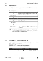
B
76
62**
17*
424
650
689
C
95
66
161
120
60
280
26
M6
24
23
26
Ø20
z
B
A
-30...0
0...+70 (+200)
10
58
8
0548-990/52g
Page 40 of 98
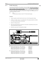
Mounting and operating instructions
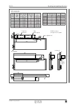
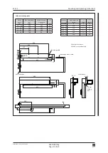
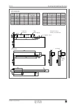
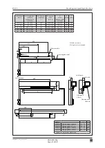
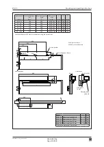
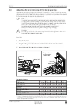
DIN right = as shown
DIN left = mirror-inverted
Chassis profile
Lintel depth
Lower edge door frame
Sliding bolt
14 mm
Clamping piece
standard
Axis of rotation
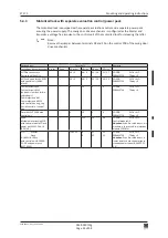
Lintel depth
(mm)
Min. width door
leaf
(mm)
Max. door opening
angle
(°)
Rod assem
-
blies
(art. no.)
A
(mm)
B
(mm)
C
(mm)
-30...+20
740
105
0548-105
140
280
620
21...30
730
105
0548-105
130
280
620
31...40
720
105
0548-105
120
280
620
41...60
720
100
0548-105
120
280
620
61...70
720
95
0548-105
120
280
620
-30...+200
870
105
0548-105/02
60
385
830
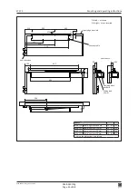
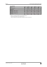
Options
*
**
0548-114
Clamping piece standard
10...18
62
0548-124
Clamping piece -13 mm
10...12
49
0548-125
Clamping piece +20 mm
10...38
82
0548-126
Clamping piece +50 mm
10...68 112
adjust the dimensions accordingly
With lintel depths >150 mm we recommend using the normal rods.

