ETS 73
0548-990-51---60g_2019.10.indd
0548-990/52g
Page 52 of 98
Mounting and operating instructions
5.3
External elements
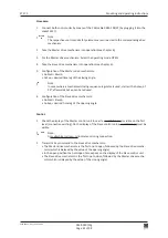
1. Mount all the required control and safety elements at their respective place.
2. Lead the cables of the elements up to the drive mechanism (by customers).
3. Connect the cables according to the diagram E4-0141-713_ECO (in the appendix).
Note:
If an electric lock is provided, its connection rating is 24 VDC and max. 0,8 A (or
24 VAC/1,5 A by customers). It should be designed for a duty cycle of 100 %. The elec
-
tric lock locks the door leaf in the desired operating modes and is configurable.
Attention:
For the Inverse application we advise to use an electric lock or a holding magnet which
maintains the door leaf in the closed position and must answer the following require
-
ments:
• tested and homologated for escape and rescue ways
• opening also under preload (load-independent unlocking without jamming)
• 24 VDC / 100 % duty cycle
• opening without mains power (normally open)
Without this electric lock, the drive mechanism needs to apply a continuous closing
pressure and push the leaf against the spring power (at the cost of increased power
consumption).
If with electric lock or holding magnet
The starting delay TDelay must be > 0 s and
the relieving force during unlocking FDelay must be adjusted in accordance.
In case the Inverse application is used for installations RWA (smoke and heat exhaust
vent solution), it is compulsory to use the drive mechanism ETS 64-R!

