ETS 73
0548-990-51---60g_2019.10.indd
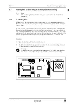
dAxis
–
+
dAxis
–
+
Joystick
Display
dAxis
5cm
Ao
95°
Press
Down
Rod
STD-PH
0548-990/52g
Page 56 of 98
Mounting and operating instructions
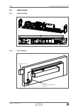
Mounting plate (option)
6
COMMISSIONING
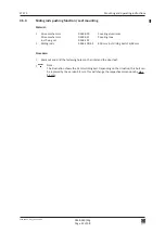
Warning:
During the setting-up procedure (which must only be carried out by experts), the safety
devices (radar, sensors, ...) are switched off!
Before initiating the setting-up procedure, it is important to make sure that neither
persons nor objects remain within the danger area of the moving door leaf, in order to
avoid injuries or damages!
Attention:
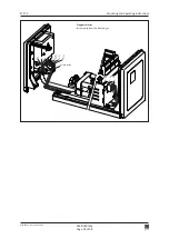
Make sure that the motor connector plug has been correctly plugged into the control
unit (see chapter 4.1 and 4.2).
Procedure:
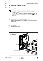
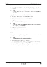
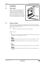
1. Switch on the mains supply switch on the side cover
(power-up).
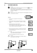
2. Using the joystick, adjust the display direction: Move the joystick
downward once
the display direction is switched to a readable
position.
3. Programming the type of rod assembly Rod:
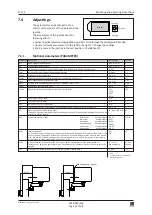
Move the joystick to the left/to the right (see parameter chap
-
ter 7.4). Validate the correct type of rod assembly by means of OK:
In the rest position, shortly push in the joystick.
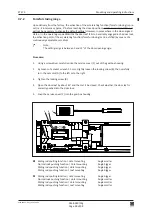
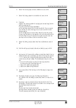
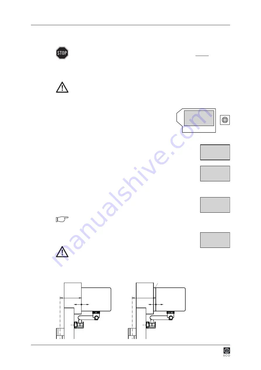
4. Adjust the distance dAxis (distance in cm between the rotation axis
of the door hinges and the mounting level of the drive mechanism
see illustration below).
Note:
dAxis is an approximate value. Depending on the installation
situation, dAxis may have to be adapted.
5. Adjust the opening angle Ao and validate by means of OK.
Attention:
The steps 4 and 5 are influenced by the installation measures/
distance between the door hinges.

