ETS 73
0548-990-51---60g_2019.10.indd
0548-990/52g
Page 61 of 98
Mounting and operating instructions
Procedure:
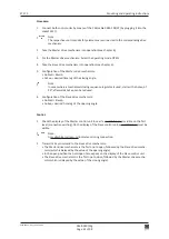
1. Connect both control units by means of the CAN cable 0383-194/07 (by plugging it into the
socket X117).
Note:
The respective control and safety elements are connected to the corresponding drive
mechanism.
2. Take the Master drive mechanism into operation (see chapter 6).
3. For the Master drive mechanism: Select the operating mode OPEN.
4. Take the Slave drive mechanism into operation (see chapter 6).
5. Configuration of the Master drive mechanism:
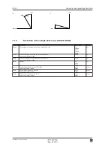
• DubleD = MastA
• AcSeq = desired time lag of the closing angle.
Note:
In cases where a mechanical closing sequence regulator is used, start with a AcSeq of
90°; afterwards AcSeq can be reduced.
6. Configuration of the Slave drive mechanism:
• DubleD = SlaveA
• AoSeq = desired time lag of the opening angle.
Control:
1. Check the display of the Master control unit to see if a small black (m) is visible on the first
level (connection existing). On the display of the Slave control unit, a small black (s) must be
visible.
Note:
A small white (m) resp. (s) indicates: missing connection.
2. Transmit a Key command to the Slave drive mechanism:
• The Master-drive mechanism is the first one to open, followed by the Slave drive mecha
-
nism (which is delayed by the value of the opening angle).
• In the open position the hold-open time expires on the display of the Slave control unit.
• The Slave drive mechanism is the first one to close, followed by the Master drive mecha
-
nism which is delayed by the value of the closing angle).

