ETS 73
0548-990-51---60g_2019.10.indd
A
A
A
A
A
A
!
0548-990/52g
Page 20 of 98
Mounting and operating instructions
4.3
General
Warning:
The fastening bases must provide sufficient solidity. If necessary they have to be rein
-
forced by the appropriate means.
Attention:
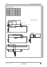
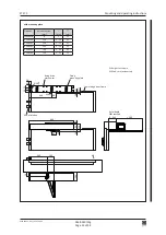
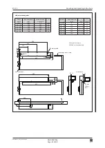
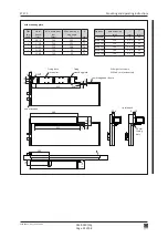
The maximum admissible undulation of the fastening base is 1 mm. The drive me
-
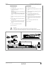
chanism must be fastened without torsion and perpendicularly, using all the six fixing
holes!
Warning:
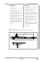
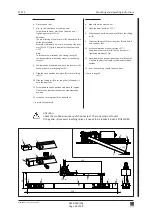
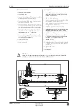
Tighten all the six M6 fixing screws (A) with a torque of
10 Nm
!
Note:
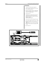
Depending on the assembly situation of the drive mechanism, it may be advisable to
install the program selector on the opposite side (in order to guarantee an optimal
operating facility). Should this be required, the work must be carried out according to
chapter "Electrical connections".
Note:
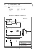
In cases where it is planned to integrate an open position stop piece into the drive
mechanism (option), this stop piece must be mounted prior to the rod assembly (see
instructions for option 0548-992/02 resp. 0548-992/52).
Note:
In case FLATSCANs are planned, they must be mounted according to chapter 13.9.


