ETS 73
0548-990-51---60g_2019.10.indd
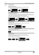
Joystick
Display
R0+R1-
FP-RP-
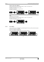
Joystick
Display
R0xR1-
FP-RP-
0548-215
0548-990/52g
Page 95 of 98
Mounting and operating instructions
13.8
Optional PCBs
All the optional PCBs are plugged into the control unit via a universal connector. A maximum
number of two optional PCBs can be combined.
Attention:
All optional PCBs must only be plugged into/removed from the control unit after the
dive unit has been disconnected from the power supply source!
13.8.1
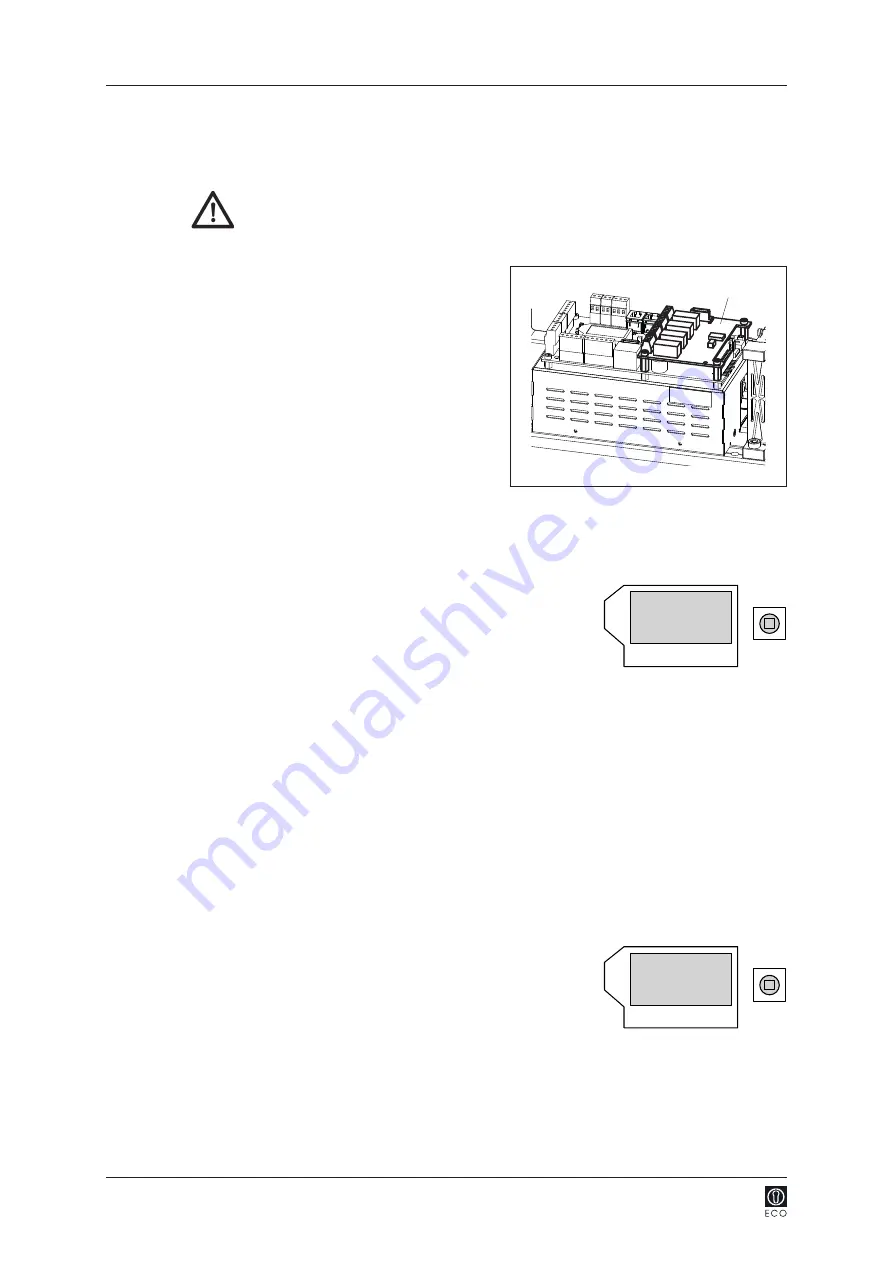
Relay PCB
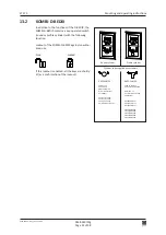
The relay PCB (blue) offers four outputs to be
freely used by the customer.
Commissioning:
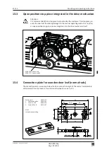
1. Addressing of the relay PCB by means of DIP-
Switch:
DIP-Switch Addr0 or Addr1.
2. Switch-on the main installation swtich on
the drive mechanism
the relay PCB is
automatically identified.
The identified relay PCB is displayed as follows in the diagnostic menu:
R0 Addr0
R1 Addr1
FP Fire protection PCB
RP Radio PCB
+
identified and ready for operation
-
neither identified nor registered
e
defective or error
x
removed
3. Enabling of the desired function per relay: under Settings
Configuration RC0.1 up to RC0.4
(for Addr 0) and RC1.1 up to RC1.4 (for Addr 1).
Remove the relay PCB:
1. Switch-off the main installation swtich on the drive mechanism
.
2. Remove the relay PCB.
3. Switch-on the main installation swtich on the drive mechanism
.
Display:
E60/00
Addr0
E60/10
Addr1
4. Select menu: Diagnostics
R0-R1-...
R0xR1-...
R0-R1x...
R0xR1x...
5. In the rest position, press in the joystick: Reset OK?
The relay PCB is deleted from the
configuration.

