pag.11
LB 472
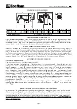
Blu 1700.1÷2000.1 P AB
B
LANDIS LGB 22 UP-CYCLE
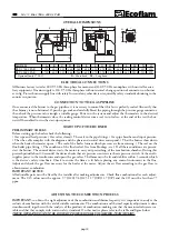
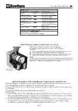
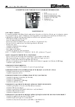
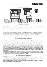
The control box starts the burner fan, to carry out the prepurging
of the combustion chamber, and cheks the vent air pressure
through the air pressure switch. At the end of prepurging, the
ignition transformer cuts-in and generates a spark between the
electrodes. At the same time the two gas valves open (Vs safety
valve and Vl Low flame working valve). The total safety, in case of
missed ignition or casual burner's flame-out, is granted by a ionisation probe which cuts-in and sets the burner shut-
down within the safety time. In case of gas lack or a major pressure drop, the minimum air pressure switch shuts down
the burner.
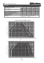
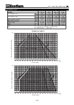
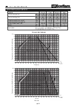
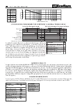
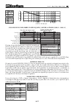
AIR EXCESS (%)
AIR FACTOR
10
10
20
30
40 50 60
70
80
90
100
200
300 400
500
600
700
800
900
1000
2000
1,1
1,15
1,2
1,2
1,2
1,25
1,3
15
20
25
30
THERMAL POWER (kW)
Natural Gas
CO
2
9,6%
CO
<50 ppm
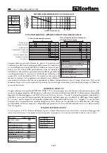
t1
t2
t3
t2
t3
t5
t4
t6
t1
t5
t4
Lock out lamp
Flame detection
Gas valve
High flame ON/OFF
Transformer
Air pressure switch
Motor
Gas pressure switch
Normal operative cycle ignition
Operative cycle with flameless
Description
t1 pressure switch control time-out
9"
t2 time-out for air pressure confirmation 3"
t3 prewashing time
30"
t4 safety time
3"
t5 preignition time
3"
t6 time-out to enable fuel 2nd valve
8"
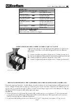
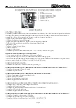
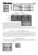
SATRONIC DMG 972 CONTROL INFORMATION SYSTEM
The SATRONIC DMG 972 control is a micro-processor control which provides information about the current opera-
tion of the burner and the cause of any faults. The information is available by reading the “flash code” at the red LED
within the lockout reset button as detailed below. By the use of additional monitoring equipment a short history of
recorded faults is also available. There are two types of additional monitoring devices available from Satronic Ltd. The
“satropen” is a small pocket reader designed to give a visual read out of status, flame current and supply voltage.
Computer software is available to allow access to the current information and stored data.
FAULT DISPLAY MESSAGES
On burner failure the red LED is permanently illuminated for a period of approximately 10 seconds, followed by a
brief “dark phase”, then one of the following flash codes will indicate the cause of the fault. This indication will repeate
as long as the lockout reset button is not reset.
Message
Flash-Code
waiting for air proving
❘ ❘
.
switch
pre-purge (tv1)
❘ ❘ ❘
.
pre-ignition (tvz)
❘ ❘ ❘ ❘
.
safety time (ts)
❙ ❘
.
delay 2nd stage (tv2)
❙ ❘ ❘
.
running
❘
_
low mains voltage
❘ ❙ ❙
_
Flash-Code Key
short pulse
❘
long pulse
❙
short pause
.
long pause
_
L.P.G.
CO
2
11,7%
CO
<50 ppm


