background image

420010244904

25.02.2019

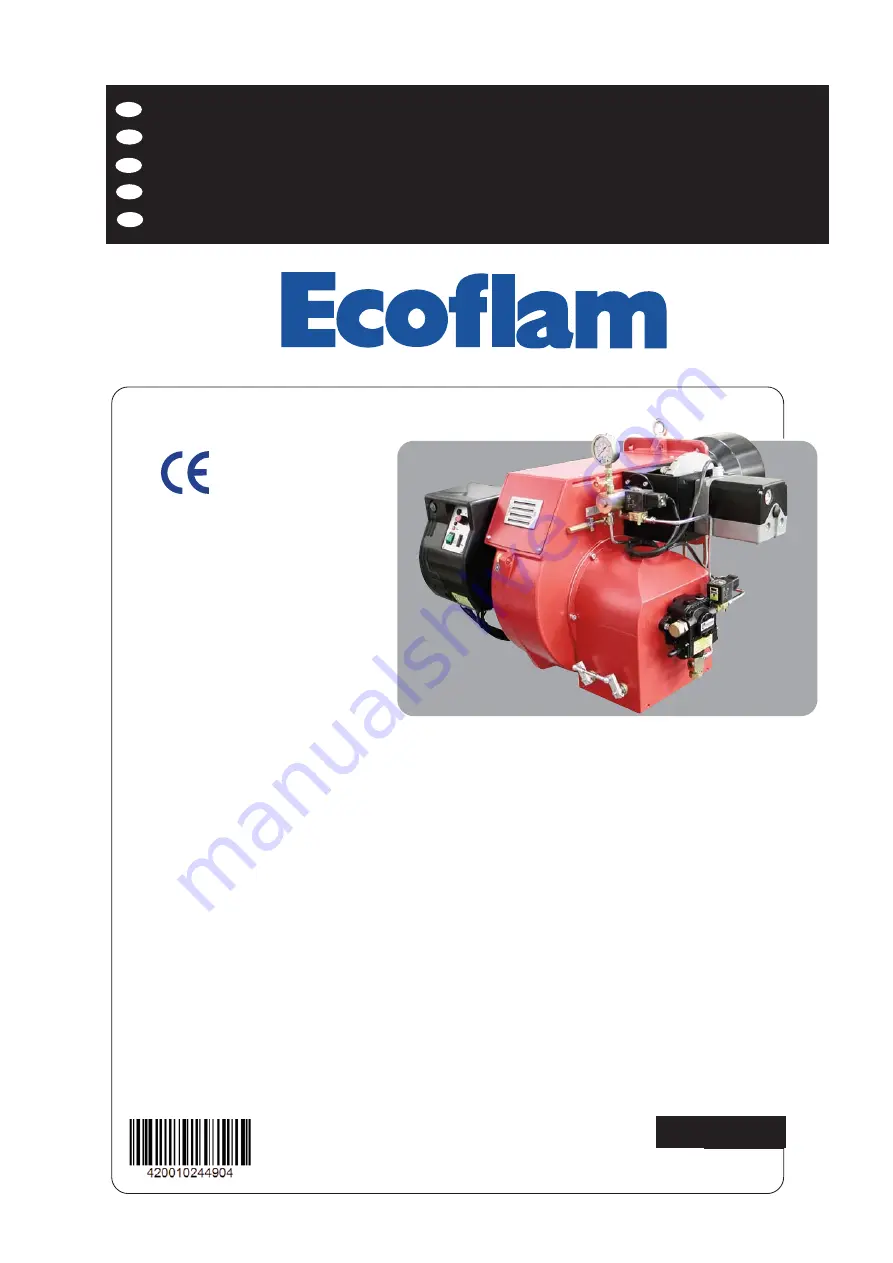
MAIOR P 150.1 PR
MAIOR P 200.1 PR

BRUCIATORI DI GASOLIO
OIL BURNERS
BRULEURS A MAZOUT 
QUEMADOR DE GASOLEO

ДИЗЕЛЬНЫЕ ГОРЕЛКИ

h

f

IT

EN

FR

ES

RU

Summary of Contents for Maior P 150.1 PR

Page 1: ...420010244904 25 02 2019 MAIOR P 150 1 PR MAIOR P 200 1 PR BRUCIATORI DI GASOLIO OIL BURNERS BRULEURS A MAZOUT QUEMADOR DE GASOLEO ДИЗЕЛЬНЫЕ ГОРЕЛКИ h f IT EN FR ES RU ...

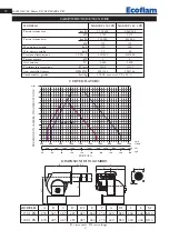
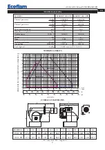
Page 2: ...ta termica min kcal h 510 000 612 000 kW 592 710 Max portata gasolio kg h 150 200 Min portata gasolio kg h 50 60 Tensione alimentazione 50 Hz V 230 400 230 400 Potenza motore kW 3 4 Giri minuto Nº 2 800 2 800 Trasformatore accensione kV mA 10 30 13 35 App controllo fiamma SIEMENS LMO 44 LMO 44 Combustibile gasolio kcal kg 10 200 max visc 1 5 E a 20 C CURVE DI LAVORO 400 600 800 1000 1200 1400 1600...

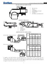
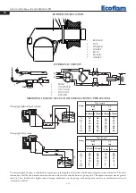
Page 3: ...za tra la valvola di fondo e l asse della pompa del bruciato re La depressione non deve superare 0 45 bar un valore maggiore potrebbe causare un deterioramento della pompa con conseguente aumento dei rumori meccanici ed eventuale rottura ALIMENTAZIONE COMBUSTIBILE H H H m ø 14 mm ø 16 mm 0 0 5 1 2 3 3 5 22 25 30 35 38 40 38 45 50 60 70 80 ø 14 mm ø 16 mm 16 18 20 25 29 31 29 33 37 44 52 55 J 7 m H...

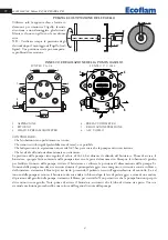
Page 4: ...valore di 22 24 bar durante il collaudo del bruciatore Prima di avviare il bruciatore spurgare l aria contenuta nella pompa attraverso la presa del manometro Riempire le tubazioni di gasolio per facilitare l innesco della pompa Avviare il bruciatore e verificare la pressione di alimentazione della pompa Se l innesco della pompa non dovesse avvenire durante il primo prelavaggio con conseguente succ...

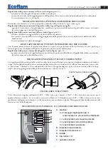
Page 5: ...uta Il tipo di combustibile che deve essere adatto al bruciatore Il collegamento dei termostati caldaia e delle varie sicurezze Il senso di rotazione del motore La corretta taratura della protezione termica del motore Quando tutte queste condizioni sono verificate e soddisfatte si può procedere con il collaudo del bruciatore Dare tensione al bruciatore L apparecchiatura di controllo alimenterà il ...

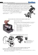
Page 6: ...lio 2 3 bar nella linea di ritorno nel regolatore Rapporto di portata 1 a 3 bar SIEMENS SQM 50 481A2 Togliere il coperchio per accedere alle camme di regolazione Lo spostamento delle camme va effettuatocon l ausilio dell apposita chiavetta in dotazione Descrizione I Camma di regolazione aria Alta Fiamma lavoro II Camma di regolazione aria accensione Minima potenza III Camma di regolazione aria Bas...

Page 7: ...e intermedie del gasolio vedere figura part 3 agendo con una chiave a brugola adeguata modificare la posizione della lamina di guida della camme avvitando la portata aumenta svitando diminuisce REGOLAZIONE POSIZIONE TESTA DI COMBUSTIONE La regolazione della posizione della testa di combustione viene effettuata per ottenere il miglior rendimento di combu stione Nelle applicazioni alle portate minim...

Page 8: ...a Portata d aria di combustione eccessivamente elevata in rapporto alla portata dell ugello Il bruciatore si accende ma va in blocco subito dopo Apparecchiatura di controllo difettosa Ugelli otturati Ugelli eccessivamente usurati La fotocellula non vede la fiamma Filtri intasati Pressione gasolio troppo bassa Portata d aria di combustione eccessivamente elevata in rapporto alla portata dell ugello...

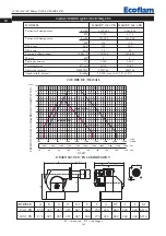
Page 9: ...ransformer kV mA 10 30 13 35 Control box SIEMENS LMO 44 LMO 44 Fuel light oil kcal kg 10 200 max visc 1 5 E a 20 C MODELS A B C D D1 E F G H1 I L M P 150 1 PR 850 385 465 285 485 660 250 420 680 240 240 M14 P 200 1 PR 870 405 465 285 485 660 270 420 680 240 240 M14 D short head D1 long head 400 600 800 1000 1200 1400 1600 1800 0 2 4 6 8 40 mbar kcal h x 1000 kg h kW 60 80 100 120 140 160 180 10 12...

Page 10: ... burner s pump axle The depression must not be greater than 0 45 bar should it be higher some damages could occur to the pump with consequent increase in mechanical noises and eventually a failure MAXIMUM LENGTH OF SUCTION LINES FOR TWO PIPE SYSTEM H H H m ø 14 mm ø 16 mm 0 0 5 1 2 3 3 5 22 25 30 35 38 40 38 45 50 60 70 80 ø 14 mm ø 16 mm 16 18 20 25 29 31 29 33 37 44 52 55 J 7 m H m ø 14 mm ø 16 ...

Page 11: ... is not greater than 0 45 bar to avoid pump s cavitation That check valve is suitably designed for the duty The pump pressure is set at a value of 22 24 bar during the testing of burners Before starting the burner bleed the air in the pump through the gauge port Fill the piping with light oil to facilitate the pump priming Start the burner and check the pump feeding pressure In case the pump primi...

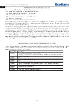
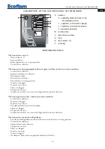
Page 12: ...sealed The type of fuel which must be suitable for burner The connection of boiler s thermostats and all the safeties The motor rotation direction The correct calibration of the motor s thermal protection When all the above mentioned conditions are checked and accomplished it is possible to go on with burner s tests Power the burner The control box feeds the ignition transformer and the burner s m...

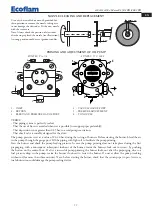
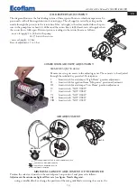
Page 13: ... supply is therefore reached when the pres sure in the pump line is about 22 24 bar and the return line is fully closed min oil supply when the return line is fully open Relevant pressure readings in the return line are as follows max oil supply 22 24 bar in the pump 14 15 bar in the return min oil supply 2 3 bar Rate of adjustment 1 to 3 bar AIR ADJUSTMENT Part 1 Part 2 Part 3 COMMUTATORE 0 AUTO ...

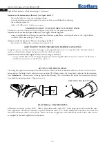
Page 14: ...ustment is made as outlined below Repeat the operation for the other cam points Adjustment the intermediate light oil flow rates see figure detail 3 using a suitable Allen wrench change the position of the cam guide blade if you screw it down the flow rate is reduced if you unscrew it the flow rate increases ELECTRICAL CONNECTIONS All burners are factory tested at 400V 50Hz 3 phase for motors and ...

Page 15: ...Control box is defective Nozzles are clogged Nozzles are too worn The photocell does not detect the flame Filters are clogged Oil pressure too low Combustion air flow rate excessively high related to nozzle s flow rate The burner does not switch to High flame Low flame and High flame manual switch on control board is in wrong position Control box is defective Solenoid valve coil is defective Oil p...

Page 16: ...2 040 000 kW 1 780 2 372 Puissance thérmique min kcal h 510 000 612 000 kW 592 710 Débit max kg h 150 200 Débit min kg h 50 60 Tension d alimentation 50 Hz V 230 400 230 400 Moteur kW 3 4 Tours par minute Nº 2 800 2 800 Transformateur kV mA 10 30 13 35 Coffret de sécurité SIEMENS LMO 44 LMO 44 Combustible mazout kcal kg 10 200 max visc 1 5 E a 20 C PRESSION DANS LA CHAMBRE DE COMBUSTION DEBIT MODE...

Page 17: ...non retour et l axe pompe du brûleur La dépression en aspiration ne devra pas dépasser les 0 45 bar en cas de dépression plus importante la pompe pourrait s endommager avec une conséquente augmentation des bruits méca niques et a la limite une panne totale H H H m ø 14 mm ø 16 mm 0 0 5 1 2 3 3 5 22 25 30 35 38 40 38 45 50 60 70 80 ø 14 mm ø 16 mm 16 18 20 25 29 31 29 33 37 44 52 55 J 7 m H m ø 14 ...

Page 18: ...ur se met en sécurité par faute d une chute de pression du fioul dans la pompe rearmer la mise en sécurité pour le rédémarrer Ne jamais laisser que la pompe tourne sans fioul pendant plus que trois minutes Dans le cas où l amorçage de la pompe ne s effectue pas pendant le premier prebalayage déclencher la mise en sécurité du brûleur Note avant de démarrer le brûleur s assurer que le tuyau de retou...

Page 19: ...n sécurité du brûleur Pour obtenir une combustion optimale il faudra réguler la portée de l air en 1re et 2me ALLURE suivant les instruc tions données plus après Pendant cette phase on pourra passer manuellement de la position de 2me Allure II à celle de 1re Allure I et viceversa à l aide de l interrupteur de 1re 2me ALLURE A la fin des réglages laisser l interrupteur en position II 2me ALLURE La ...

Page 20: ...on utilisé RÉGLAGE DE LA PRESSION DE RETOUR FIOUL Le diagramme représente le système de réglage du retour de fioul pour ces types de brûleurs qui incorpo rent un gicleur avec retour variable progressif Le débit du fioul peut être modifié au moyen du gicleur de retour en modifiant la pression dans le retour On obtient le débit maximum de fioul quand la pression de la pompe est d environ 22 24 bars ...

Page 21: ...ssance minimale de l air voir immage partie 1 dévisser la clé à six pans du fermer de la volet d air tourner la volet d air jusqu à al accomplissement de la débit de l air correct déterminé du l analyse de combustion resserrer nouveau la clé à six pans REGLAGE DE LA PUISSANCE MAXIMALE DU BRULEUR Positionner le commutateur qui se trouve dans le tableau de borde dans la position 1 et agir comme il s...

Page 22: ...cessivement usés Filtres bouchés Pression fioul trop faible Portée de l air comburante trop élevée par rapport à la portée du gicleur Le brûleur s allume mais se met en de sécurité peu après Coffret de sécurité défectueux Gicleurs bouchés Gicleurs excessivement usés La photocellule n aperçoit pas la flamme Filtres bouchés Pression fioul trop faible Portée de l air comburante trop élevée par rappor...

Page 23: ...rmica mín kcal h 510 000 612 000 kW 592 710 Caudal máx de gasóleo kg h 150 200 Caudal mín de gasóleo kg h 50 60 Aliment eléct 50 Hz V 230 400 230 400 Potencia del motor kW 3 4 Revol por minuto Nº 2 800 2 800 Transformador de encendido kV mA 10 30 13 35 Equipo de control de la llama SIEMENS LMO 44 LMO 44 Combustible gasóleo kcal kg 10 200 max visc 1 5 E a 20 C PRESION EN LA CAMARA DE COMBUSTION CAU...

Page 24: ...retorno y el eje bomba del quemador La depresión no debe superar los 0 45 bar una depresión mas grande podría perjudicar el funcionamiento de la bomba con consecuente aumento del ruido mecánico y al final una ruptura ALIMENTACION DEL COMBUSTIBLE H H H m ø 14 mm ø 16 mm 0 0 5 1 2 3 3 5 22 25 30 35 38 40 38 45 50 60 70 80 ø 14 mm ø 16 mm 16 18 20 25 29 31 29 33 37 44 52 55 J 7 m H m ø 14 mm ø 16 mm ...

Page 25: ... quemador purgar el aire contenido en la bomba a través la toma para el manómetro Llenar las tuberías con gasóleo para facilitar el cebado de la bomba Arrancar el quemador y comprobar la presión de alimenta ción de la bomba Si se verificases que el cebado de la bomba no se efectúa durante el primer prebarrido con conse cuente sucesivo bloqueo del quemador rearmar el bloqueo para arrancarlo nuevame...

Page 26: ...o de combustible que debe ser adecuado para el quemador Las conexión de los termostatos de caldera y de los dispositivos de seguridad El sentido de rotación del motor La regulación correcta de la protección térmica del motor Cuando todas estas condiciones se cumplen es posible de proceder con las pruebas del quemador Alimentar el quemador El equipo de control alimenta al mismo tiempo el transforma...

Page 27: ...regulación del retorno de gasoleo para estos tipos de quemadores los cuales han incorporado un un inyector con retorno variable progresivo El caudal del gasoleo puede variarse a través del inyector de retorno cambiando la presión en el retorno El caudal máxi ma de gasoleo se obtiene cuando la presión de la bomba es de unos 22 24 bar y el retorno está completamente cerrado El caudal mínimo del gaso...

Page 28: ...jar nuevamente la tuerca de bloqueo REGULACIÓN DE LAS POTENCIAS INTERMEDIAS DEL QUEMADOR Obrar el servomotor con el conmutador apertura o cierre y ponerlo en posición 0 para bloquear la carrera Para la regulación proceder como sigue Regulación de los caudales intermedios del gas véase la ilustración part 3 obrar sobre la varilla de regulación con una llave hexagonal apropiada y modificar la posici...

Page 29: ... Filtros obstruidos Presión del gasóleo demasiado baja Caudal del aire de combustión demasiado alta en relación al caudal del inyector El quemador se enciende pero se pone pronto en seguridad Equipo de control averiado Inyectores obstruidos Inyectores demasiado desgastados La fotorresistencia no percibe la llama Filtros obstruidos Presión gasóleo demasiado baja Caudal del aire de combustión demasi...

Page 30: ... 800 2 800 Трансформатор розжига кВ мА 10 30 13 35 Устройство контроля пламени SIEMENS LMO 44 LMO 44 Топливо дизельное топливо ккал кг 10 200 макс вязкость 1 5 E при 20 C МОДЕЛЬ A B C D D1 E F G H1 I L M P 150 1 PR 850 385 465 285 485 660 250 420 680 240 240 M14 P 200 1 PR 870 405 465 285 485 660 270 420 680 240 240 M14 D короткая огневая головка D1 длинная огневая головка 400 600 800 1000 1200 14...

Page 31: ...ется расстоянию между донным клапаном и осью насоса горелки Разряжение не должно превышать 0 45 бар превышение данной величины может повлечь за собой повышенный износ насоса повышенный уровень шума и в конечном итоге выход из строя насоса H H H m ø 14 mm ø 16 mm 0 0 5 1 2 3 3 5 22 25 30 35 38 40 38 45 50 60 70 80 ø 14 mm ø 16 mm 16 18 20 25 29 31 29 33 37 44 52 55 J 7 m H m ø 14 mm ø 16 mm 0 0 5 1...

Page 32: ...ля того чтобы избежать кавитации насоса Что установленный донный клапан имеет требуемые размеры Во время заводских испытаний горелки насос тарируется на давление в 22 24 бар Перед запуском горелки стравите через гнездо отбора давления содержащийся в насосе воздух Для облегчения пуска насоса заполните топливопровод топливом Запустите горелку и проверьте создаваемое насосом давление Если запуск насо...

Page 33: ...льной и минимальной мощности руководствуясь при этом инструкциями приведенными далее Во время регулирования с помощью переключателя ступеней мощности можно вручную переключаться с максимальной II на минимальную I мощность и наоборот По завершении регулировки переключатель устанавливается в положении II максимальная мощность На случай аварийной блокировки горелки предусмотрена система диагностики п...

Page 34: ...братное давление топлива при минимальной мощности горелки форсунка 2 3 бар СЕРВОПРИВОД ВОЗДУШНОЙ ЗАСЛОНКИ SIEMENS SQM 50 481A2 Для доступа к регулировочным кулачкам снять крышку Регулирование кулачков производится входящим в комплект ключом Описание Ручная регулировка I Кулачок для регулировки расхода воздуха на 2 й ступени II Концевой выключатель положения воздушной заслонки при гашении горелки I...

Page 35: ...РЕЛКИ НА СРЕДНЕЙ МОЩНОСТИ Переключателем включить сервопривод закрывание или открывание и прервать его ход переведя пере ключатель в положение 0 выполнить регулировку по приведенным ниже инструкциям Повторить эту опе рацию для всех остальных кулачков Регулировка расхода дизтоплива на средней мощности горелки см рис деталь 3 при помощи шестигранного гаечного ключа изменить изгиб направляющей пласти...

Page 36: ...кие предохранители Термостаты котла не замыкают цепь Вышла из строя контрольная аппаратура После предварительной продувки розжиг не происходит следует аварийная блокировка горелки Вышла из строя контрольная аппаратура Вышел из строя трансформатор Засорились электроды Вышли из строя электроды Неправильно установлены электроды Засорились форсунки Форсунки сильно изношены Засорились фильтры Слишком н...

Page 37: ...37 420010244904 Maior P 150 1 PR 200 1 PR IT EN FR ES RU ...

Page 38: ...38 420010244904 Maior P 150 1 PR 200 1 PR IT EN FR ES RU ...

Page 39: ...39 420010244904 Maior P 150 1 PR 200 1 PR IT EN FR ES RU ...

Page 40: ...DIFICATION MAIOR P 150 1 200 1 PR A POZZOBON 07 07 2014 2 420110137200 1 A RIGONI LANDIS SQM 50 481A2 B RB14PC068 LANDIS LOA 44 LMO 44 F 1 E D 2 3 4 C B A 1 2 3 4 5 6 7 8 F E D 5 6 7 C B 8 A 12 4 3 2 1 11 FMV 97 98 FMV 95 96 5 S R T N 7 6 9 8 10 7 8 9 6 5 4 2 3 1 11 12 10 12 10 11 3 1 2 6 5 4 7 8 9 13 7 27 26 6 17 25 5 4 15 24 16 1 23 14 13 22 3 12 21 N 1 11 2 M LANDIS SQM 50 481A2 HLF 32 12 11 31...

Page 41: ...ORMATEUR D A LLUMAGE TRANSFORMADOR LOCK OUT LAMP LAMPE DE SECURITE ESPIA DE BLOQUEO MOTOR FAN MUTEUR VENTILATEUR MOTOR VENTILADOR ANTJAMMING FILTER FILTRE ANTIPARASITES FILTRO DE PROTECION ANTIDISTURBIO FUSE FUSIBLE FUSIBLE CONTATTORE MOTORE VENTILATORE REMOTE CONTROL SWITCH FAN MOTOR CONTACTEUR MOTEUR VENTILATEUR LAMPE DE FONCTIONNEMENT ESPIA DE FUNCIONAMIENTO WORKING LAMP SAFETY THERMOSTAT THERM...

Page 42: ...PR 200 1 PR IT EN FR ES RU MAIOR P 150 1 200 1 PR 10 28 29 47 38 42 43 44 46 45 6 41 30 48 21 7 8 9 13 MAIOR P 200 1 14 15 12 11 18 17 16 49 31 50 40 39 3 1 2 19 36 35 33 34 37 20 32 FI N D E R 27 26 0 AUTO 0 I 22 25 25 24 23 51 52 ...

Page 43: ...65323067 65323067 23 INTERRUTTORE DI LAVORO MAIN SWITCH cod 40100I1509 65323064 65323064 24 PORTA FUSIBILE FUSE HOLDER FUSIT FH B 528 65322181 65322181 25 LAMPADA LAMP EL N SC4 65322053 65322053 26 ZOCCOLO RELE RELAY BASE FINDER 95 75 65323152 65323152 27 RELE FINDER RELAY FINDER 40 50 65323142 65323142 28 VENTOLA FAN 280 x 140 65321798 65321798 29 CONVOGLIATORE AIR CONVEYOR 65320643 65320643 30 C...

Page 44: ...322181 25 LAMPE ESPIA EL N SC4 65322053 65322053 26 SOCLE DE RELAIS BASE DEL RELE FINDER 95 75 65323152 65323152 27 RELAIS FINDER RELE FINDER FINDER 40 50 65323142 65323142 28 TURBINE VENTILADOR 280 x 140 65321798 65321798 29 CONVOYEUR D AIR REJILLA DEFLECTORA 65320643 65320643 30 BOITE D AIR CIERRE EN ASPIRACIÓN 65320555 65320555 31 SERVOMOTEUR MOTORREGULADOR SQM50 481A2 65322902 65322902 32 SUPP...

Page 45: ...3067 65323067 23 РАБОЧИЙ ВЫКЛЮЧАТЕЛЬ cod 40100I1509 65323064 65323064 24 ГНЕЗДО ПРЕДОХРАНИТЕЛЯ FUSIT FH B 528 65322181 65322181 25 ЛАМПОЧКА EL N SC4 65322053 65322053 26 МОНТАЖНАЯ ПЛАСТИНА РЕЛЕ FINDER 95 75 65323152 65323152 27 РЕЛЕ FINDER FINDER 40 50 65323142 65323142 28 ВЕНТИЛЯТОР 280 x 140 65321798 65321798 29 ВОЗДУХОВОД 65320643 65320643 30 КОЖУХ ВОЗДУХОВОДА 65320555 65320555 31 ЭЛЕКТРОПРИВОД...

Page 46: ...RU ES FR EN IT 420010244904 Maior P 150 1 PR 200 1 PR 46 ...

Page 47: ...47 420010244904 Maior P 150 1 PR 200 1 PR IT EN FR ES RU ...

Page 48: ...CIATORI S p A reserves the right to make any adjustments without prior notice which it considers necessary or useful to its products without affecting their main features La Maison ECOFLAM BRUCIATORI S p A se réserve le droit d apporter les modifications qu elle jugera nécessaires ou utiles à ses produits sans pour autant nuire à leurs caractéristiques principales ECOFLAM BRUCIATORI S p A se reser...

Reviews: