background image

56 

www.ecoflam-burners.com

420010372902

RU

Символ

Неисправность

Причины

Способ устранения

Нет запроса на тепло

Термостаты неисправны или не 
настроены

Отрегулируй̆те или замените термостаты

Напряжение питания ниже 
минимально необходимого значения.

Понижение напряжения 
электропитания или его отсутствие. 
Неисправность блока.

Проверьте причину понижения напряжения 
или его отсутствия. 
Замените блок.

При подаче напряжения горелка 
запускается на очень короткое время 
и выключается, включение 
индикатора блокирования

Блок управления заблокирован 
вручную.

Разблокируйте блок.

Горелка не запускается.

Реле давления воздуха: не 
находится в рабочем положении. 
Неправильная настройка. 
Залипание контакта.

Осуществите новую регулировку реле 
давления. Замените реле давления.

Горелка не запускается. Низкое 
давление газа.

Недостаточное давление газа. 
Реле давления газа не настроено 
или неисправно.

Проверьте газопроводы. Очистите фильтр. 
Проверьте реле давления газа или 
замените компактный газовый блок.

Вентилятор горелки запускается. 
Горелка не запускается.

Реле давления воздуха: контакт не 
замыкается.

Проверьте датчик давления (попадание 
инородных тел) и электропроводку.

Вентилятор горелки запускается. 
Горелка не запускается.

Ложный сигнал пламени во время 
предварительной вентиляции или 
предварительного розжига.

Проверьте клапан. Проверьте систему 
отслеживания пламени.

Горелка запускается, происходит 
розжиг, затем следует аварийное 
отключение.

- Отсутствие пламени к концу 
времени безопасности. 
- Расход газа плохо 
отрегулирован. 
-  Неисправность в цепи контроля 
пламени. 
- Нет запальной искры 
- Короткое замыкание одного или 
нескольких электродов 
- Кабель или кабели розжига 
повреждены или неисправны 
- Неисправно устройство розжига 
- Блок управления и безопасности 
- Электромагнитные клапаны не 
открываются 
- Блокировка клапанов

- Отрегулируйте расход газа 
- Проверьте состояние и положение 
датчика ионизации относительно "массы". 
- Проверьте состояние и соединения 
ионизационной цепи (кабель или кабели и 
измерительные мосты). 
- Отрегулируйте электрод или электроды, 
очистите или замените их. 
- Подключите или замените кабель или 
кабели. 
- Замените устройство розжига 
- Замените блок управления 
- Проверьте электропроводку блока 
управления и внешних компонентов 
- Замените компактный газовый блок 
- Замените клапаны

Неисправность системы контроля 
пламени во время работы.

- Реле даления воздуха: контакт 
размыкается при запуске или во 
время работы. 
- Сбой пламени во время работы.

Отрегулируйте или замените реле 
давления 
Проверьте цепь ионизационного зонда. 
Проверьте или замените блок управления.

Сервис 

- Возможные неполадки 

Причины неисправностей и способы 
их устранения 

При сбое в работе должны быть 
проверены нормальные условия для 
работы горелки:  
1. Есть электрическии

̆

 ток?  

2. Есть давление газа? 
3. Газовый кран открыт? 

4. Правильно ли настроены все 
регулирующие и предохранительные 
устрои

̆

ства, такие как термостат котла, 

датчик уровня воды, электрические 
концевые выключатели? 

Если неисправность сохраняется, 
используйте таблицу ниже. 

 
Компоненты системы 
безопасности не подлежат 

ремонту; они должны заменяться 
компонентами с тем же артикулом. 


Используйте только 
оригинальные запасные части.


В случае остановки горелки, во 
избежание ущерба установке, 
не следует разблокировать го-
релку более двух раз подряд. 

Если горелка блокируется в третий 
раз, свяжитесь со службой техниче-
ской помощи. 


Примечание: после 
проведениялюбых работ:


- выполните проверку параметров 
горения в реальных условиях 

эксплуатации (дверцы закрыты,кожух 
установлен и т. д.).  
- запишите результаты в 
соответствующие документы 
 

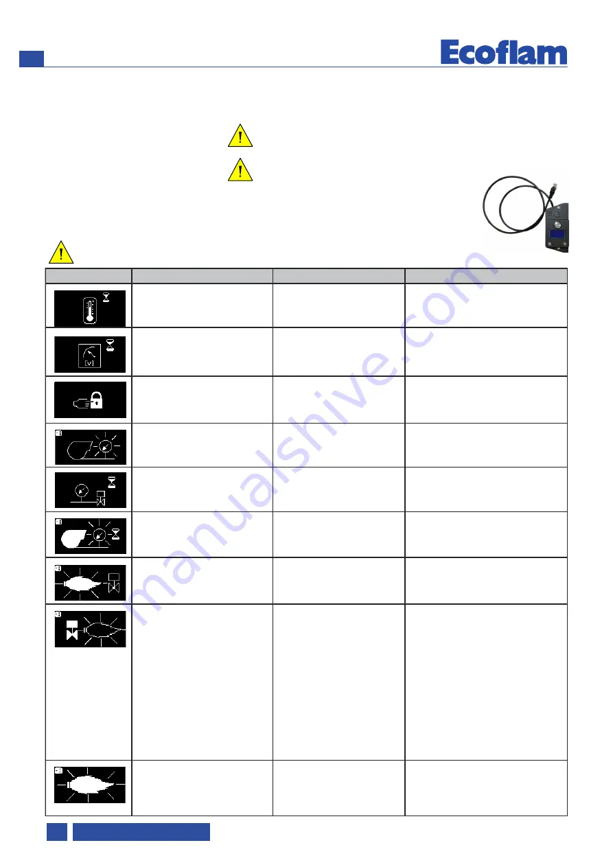
Диагностический инструмент E-BCU 
должен быть использован 
персоналом, 
выполняющим  
техническое 
обслуживание, с 
целью 
определения 
неисправности 
горелки.

WARNING

DANGER

WARNING

Summary of Contents for MAX GAS 170 P

Page 1: ...ico Sch mas lectrique Esquemas el ctrico Spare parts list Parti ricambi Pi ces de rechange Piezas de recambio GAS BURNERS EN IT FR ES RU MAX GAS 170 P MAX GAS 250 P MAX GAS 170 LN P TC SGT 230 50 TW 3...

Page 2: ...ento EN IT FR ES RU 5 Dimensions Dimensioni Dimensions Dimensiones EN IT FR ES RU 6 Operating instructions for authorised specialists EN 7 16 Istruzione per l uso per il personale qualificato IT 17 26...

Page 3: ...golamento Apparecchi a Gas Gas Appliance Regulation 2006 42 EC Direttiva Macchine Machine Directive 2011 65 UE Direttiva RoHS2 RoHS2 Directive 2015 863 UE Delegated Directive EN 676 2003 A2 2008 AC 20...

Page 4: ...60 mbar SEE GAS TRAIN MATCHING TABLE LPG input pressure Pressione di ingresso LPG Pression d entr e du gaz propane Presi n de entrada LPG LPG 16 360 mbar SEE GAS TRAIN MATCHING TABLE Air regulation Ai...

Page 5: ...aldaia Domaine de fonctionnement Le domaine de fonctionnement correspond aux valeurs mesur es lors de l homologation Elle correspond aux valeurs max mesur es sur tunnel d essai d apr s l EN 676 Pour l...

Page 6: ...Rr Sr MAX GAS 170 250 Model A B C D D1 E F G I L M N O P MAX GAS 170 P 392 202 190 180 280 280 125 201 106 130 106 130 M8 73 110 104 MAX GAS 250 P 392 202 190 180 280 280 125 201 106 130 106 130 M8 73...

Page 7: ...the burner after carefully clean around the intended area correctly dispose of all residual packaging separating the various types of material The burner must not be operated in rooms containing aggr...

Page 8: ...t emissions in terms of NOx and unburnt particles in order to maximize the heat generator efficiency Emissions can be different respect to the ones recorded in the lab because they depends a lot on th...

Page 9: ...ed off at the end of the safety period lasting no more than 3 seconds and the gas valve will close If the flame goes out during operation the gas supply is interrupted within one second A restart take...

Page 10: ...the voltage has exceeded the 178 V R Reset button lock out led RJ45 Connector for PC interface diagnostic separate item Function E BCU GAS control and safety unit KIT E BCU DIAGNOSTIC TOOL not supplie...

Page 11: ...per the boiler manufacturer s instructions Reverse flame boiler A 50 100 mm Three pass boilers A1 50 100 mm Exhaust system To avoid unfavourable noise emissions right angled connectors should not be...

Page 12: ...ating regulations for the heat generator must be observed All electrical connections must be correct The heat generator and heating system must be filled with water and the circulating pumps must be i...

Page 13: ...uested value index 0 4 5 A B A pressure in the combustion chamber mbar output kW B 1 5 1 0 0 5 0 0 0 5 1 0 1 5 2 0 2 5 3 0 3 5 4 0 4 5 5 0 5 5 6 0 40 50 60 70 80 90 100 110 120 130 140 150 160 170 180...

Page 14: ...WARNING the air pressure switch shall prevent the air pressure to go below 85 from the adjustment value in order to prevent the CO in the fumes to exceed 1 10000 ppm Min gas pressure switch The gas p...

Page 15: ...ue measured at the time of commissioning To simplify the check use a flue gas temperature indicator Burner maintenance positions After removing the screws 5 turn the burner and pull it out of the flan...

Page 16: ...n and position of the ionisation sensor in relation to earth Check the condition and connections of the ionisation ci rcuit cable s and measurement bridges Adjust clean or replace electrode s Connect...

Page 17: ...lante Luogo di installazione Installare il bruciatore dopo avere effettuato la pulizia intorno all area destinata Smaltire correttamente tutti i residui dell imballo differenziando le vari tipologie d...

Page 18: ...ruciatore installato L installatore deve rispettare le normative vigenti Per esempio sono da evitare locali con atmosfere pericolose o non ventilate Imballaggio Il bruciatore consegnato con un sistema...

Page 19: ...urezza di max 3 secondi la valvola del gas si chiude In caso di anomalia della fiamma durante il funzionamento l alimentazione del gas si interrompe nella frazione di un secondo Viene avviata una nuov...

Page 20: ...mpi estremamente stabili in dipendentemente dalle oscillazioni della tensione di rete o della temperatura am biente Il programmatore di comando e si curezza e progettato per essere sicuro in caso di s...

Page 21: ...to del gas Il collegamento della rampa gas alla rete del gas deve essere effettuato esclusivamente da un tecnico esperto autorizzato La sezione della tubazione del gas deve essere preparata in modo ta...

Page 22: ...ermico devono essere rispettate Tutti gli allacciamenti elettrici devono essere eseguiti correttamente Il generatore termico ed il sistema di riscaldamento sono pieni d acqua le pompe di circolazione...

Page 23: ...alore desiderato indice da 0 a 4 5 A B A B pressione gas in camera di combustione mbar potenza kW 1 5 1 0 0 5 0 0 0 5 1 0 1 5 2 0 2 5 3 0 3 5 4 0 4 5 5 0 5 5 6 0 40 50 60 70 80 90 100 110 120 130 140...

Page 24: ...ssostato eviter che la pressione dell aria non scenda sotto 85 del valore impostato evitando cos che il CO nei fumi superi 1 10000 ppm Regolazione del pressostato gas di minima Il pressostato gas di m...

Page 25: ...ne di semplificare il controllo installare un display per la visualizzazione della temperatura dei fumi di scarico Posizioni di manutenzione del bruciatore Dopo aver allentato la vite 5 e sganciato il...

Page 26: ...l elettrodo di rivelazione rispetto al collegamento a terra Controllare lo stato e i collegamenti del circuito di rivelazione cavo i e ponti di misurazione Regolare pulire o sostituire gli elettrodi C...

Page 27: ...ation Effectuer les op rations d installation apr s avoir nettoy tout autour de la zone destin Eliminer compl tement tous les r sidus d emballage en les triant par type de mat riau Le br leurs ne doit...

Page 28: ...a d pend beaucoup du g n rateur sur lequel le br leur est install L installateur doit respecter les normes en vigueur Par exemple viter les locaux dangereux et non ventil s Emballage Le br leur est li...

Page 29: ...secondes max la vanne gaz se ferme En cas de d faillance de la flamme pendant le fonctionnement l alimentation en gaz est interrompue en l espace d une seconde Un nouveau d marrage est lanc Si le br...

Page 30: ...programme par microprocesseur on aboutit des temps tr s stables ind pendamment des variations de la tension d alimentation lectrique ou de la temp rature ambiante Le coffret est con u avec une protect...

Page 31: ...ccordement de la rampe gaz au r seau de gaz ne peut tre r alis que par un technicien sp cialiste agr La section de la tuyauterie de gaz doit tre r alis e de telle sorte que la pression d alimentation...

Page 32: ...Les donn es de r glage ci dessus sont des r glages de base Les donn es de r glage d usine sont encadr es en gras et sur fond gris Dans un cas normal ces r glages permettent la mise en service du br l...

Page 33: ...de combustion mbar Puissance kW 1 5 1 0 0 5 0 0 0 5 1 0 1 5 2 0 2 5 3 0 3 5 4 0 4 5 5 0 5 5 6 0 40 50 60 70 80 90 100 110 120 130 140 150 160 170 180 190 200 210 220 9 5 9 8 5 8 0 1 2 3 5 5 5 5 MAX G...

Page 34: ...ur programm e en vitant ainsi que le CO des fum es ne d passe 1 10000 ppm R glage du pressostat du gas min Le pr ssostat gaz mini a la fonction de v rifier que la pression du gaz avant la vanne soit l...

Page 35: ...r la mise en service de plus de 30 C Utiliser un afficheur de temp rature des gaz de combustion pour faciliter le contr le Positions d entretien du br leur Apr s avoir desserr la vis 5 et d croch le b...

Page 36: ...uvrent pas Blocage des vannes R gler le d bit de gaz V rifier l tat et la position de la sonde d ionisation par rapport la masse V rifier l tat et les raccordements du circuit d ionisation c ble et po...

Page 37: ...instalar el quemador en la caldera prestando atenci n a no estropear la empaquetadura aislante Condiciones de instalaci n Instale el quemador despu s de realizar una cuidadosa limpieza en toda el rea...

Page 38: ...el laboratorio de prueba ya que dependen mucho del generador en el cual el quemador est instalado Embalaje El quemador se entrega con un sistema modular de embalaje cajas separadas es decir separadas...

Page 39: ...uridad se cierra En caso de fallar la llama durante el funcionamiento la alimentaci n de gas se interrumpe en el espacio de un segundo Se inicia una nueva puesta en marcha Si el quemador se pone en ma...

Page 40: ...ocesador se obtienen tiempos extremadamente estables independientes de las oscilacio nes de la tensi n en la red o de la tempe ratura ambiente El programador de comando y seguridad fue proyectado para...

Page 41: ...ara la conexi n del gas La conexi n de la rampa del gas a la red del gas tiene que efectuarla exclusivamente un t cnico experto autorizado La secci n del tubo del gas tiene que prepararse de manera qu...

Page 42: ...espetarse sus recomendaciones de utilizaci n Todas las conexiones el ctricas deben realizarse correctamente El generador de calor y el sistema de calefacci n deben estar lo suficientemente llenos de a...

Page 43: ...de 0 a 4 5 A B A B presi n en c mara de combusti n mbar potencia kW 1 5 1 0 0 5 0 0 0 5 1 0 1 5 2 0 2 5 3 0 3 5 4 0 4 5 5 0 5 5 6 0 40 50 60 70 80 90 100 110 120 130 140 150 160 170 180 190 200 210 2...

Page 44: ...por debajo del 85 del valor configurado evitando de esta forma que el CO en los humos supere el 1 10000 ppm Regulaci n del pres stato gas de m n ima El pres stato gas de m nima tiene la funci n de ver...

Page 45: ...n de funcionamiento WARNING Las operaciones de mantenimiento de la caldera debe llevarlas a cabo un t cnico especialista en calefacci n Para garantizar la realizaci n anual de los trabajos de mantenim...

Page 46: ...loqueo de las v lvulas Ajustar el caudal de gas Comprobar el estado y la posici n de la sonda de ionizaci n con respecto a la masa Comprobar el estado y las conexiones del circuito de ionizaci n cable...

Page 47: ...burners com 420010372902 RU 3 4 5 6 47 47 48 49 E BCU GAS 50 51 52 52 53 54 55 56 57 58 59 60 61 Ecoflam ISO 9001 2008 MAX GAS EN 676 20 WARNING WARNING DANGER WARNING DANGER WARNING CAUTION WARNING W...

Page 48: ...1 F6 16 113 103B 5 8 A1 10 15 MAX GAS P NOx A1 E_BCU GAS F6 M1 T1 Y 3 5 8 10 wieland 15 16 103B 113 Ecoflam WARNING BBCH 1 wieland GT KIT ACS KIT ACS MAX GAS 170 LN P TC TW MAX GAS MAX GAS 170175 LN L...

Page 49: ...49 www ecoflam burners com 420010372902 RU 24 24 1 5 A 3 2 2 3 x 2 1 1 108 106 119 1 Y12 104 F4 119 1 119 pBr Y13 119 2 F6 F4 F6 Y13 Y12 1 104 106 108 119pBr 119 1 119 2...

Page 50: ...50 www ecoflam burners com 420010372902 RU R RJ45 E BCU LINE 1 Max 5s 33s 3s 25s 5s 1s 2 3 4 4 5 6 7 8 9 C 24s E BCU GAS 170 B 178 R R RJ45 DANGER E BCU GAS...

Page 51: ...51 www ecoflam burners com 420010372902 RU 3 4 5 A A1 3 4 5 5 3 Kit LPG KITLPG MAXGAS 5 60 6 EN676 EN676 Pf Pb Pin CAUTION DANGER A 50 100 mm A1 50 100 mm OK 1 2 3 4 OK OK...

Page 52: ...52 www ecoflam burners com 420010372902 RU A 5 A 1 1 InputVoltage T P STS HLB HLF Q L N PE T P STC S3 B4 T2 N T1 L1 O KIT LPG B10 0 100 A 1 5 A E BCU B10 A A Sez A A 3 4 3 DANGER...

Page 53: ...U A B B 0 4 5 A B A B 1 5 1 0 0 5 0 0 0 5 1 0 1 5 2 0 2 5 3 0 3 5 4 0 4 5 5 0 5 5 6 0 40 50 60 70 80 90 100 110 120 130 140 150 160 170 180 190 200 210 220 9 5 9 8 5 8 0 1 2 3 5 5 5 5 MAX GAS 170 P NA...

Page 54: ...0372902 RU A B C D 15 C A B 85 CO 1 10000 I L M N 60 20 12 30 37 18 M I L 0 4 0 6 0 9 3 0 1 5 2 1 1 8 2 4 2 7 1 2 A B C D 2 5 5 10 15 50 25 3 5 30 40 45 20 I L M N n 1 n 2 n 3 n 4 Nm3 h min max C C CO...

Page 55: ...55 www ecoflam burners com 420010372902 RU 1 2 3 2 3 A B A B 1 WARNING 30 C 5 1 2 3 WARNING DANGER...

Page 56: ...56 www ecoflam burners com 420010372902 RU 1 2 3 4 E BCU WARNING DANGER WARNING...

Page 57: ...ione gas in camera di combustione mbar pression dans la chambre de combustion mbar pressi n en la c mera de combusti n mbar output kW potenza kW puissance kW potencia kW pressure in the combustion cha...

Page 58: ...5 2 0 2 5 3 0 3 5 4 0 4 5 5 0 5 5 6 0 40 50 60 70 80 90 100 110 120 130 140 150 160 170 180 190 200 210 220 230 240 250 260 9 5 10 9 8 5 8 7 5 7 0 1 2 3 4 5 6 5 5 5 5 5 5 5 pressure in the combustion...

Page 59: ...ERMOSTATO CALDAIA STC PRESSOSTATO ARIA SPA LAMPADA DI BLOCCO HLB LAMPADA DI PRIMA FIAMMA HL1 TRASFORMATORE TV MOTORE VENTILATORE MV ELETTRODO DI RIVELAZIONE ER INTERRUTTORE GENERALE CON FUSIBILE Q Ten...

Page 60: ...list Panoramica Parti di ricambio Vue d ensemble Pi ces de rechange Descripci n Piezas de recambio MAX GAS 170 P MAX GAS 250 P MAX GAS 170P 0050 0130 0010 0070 0040 0190 0260 0180 0270 0170 0160 0280...

Page 61: ...169 0130 IGNITION TRANSFORMER TRASFORMATORE TRANSFORMATEUR D ALLUMAGE TRANSFORMADOR 65323258 65323258 0140 0150 ORING ORING ORING ORING 65321061 65321061 0160 IONIZATION CABLE CAVO DI RIVELAZIONE CABL...

Page 62: ...62 www ecoflam burners com 420010372902 EN IT FR ES RU...

Page 63: ...63 www ecoflam burners com 420010372902 EN IT FR ES RU...

Page 64: ...a il diritto di apportare ai prodotti le modifiche che riterr necessarie o utili senza pregiudicarne le caratteristiche principali La maison Ecoflam Bruciatori S p A se r serve le droit d apporter les...

Reviews: