background image

B

LB 1681   

Max Gas 170 PR - 250 PR

pag.12

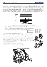
NOTE:

should it be difficult to measure the quantity of delivered litres of gas, due to the particular meter’s dial, it is

possible to repeat, sequentially, the above steps many times, so as to reach a significant amount of gas volume. In such a
case, the thermal power at the ignition shall be obtained by multiplying the ratio, between the amount of delivered
litres and the number of cumulated safety times (i.e. the value of the safety time multiplied by the number of ignitions)
by the F factor. See the following examples: Example A: MAX GAS 170 burner, nat. gas; rated thermal power of 175
kW; safety time of 3 secs; a sequence of 4 ignitions is made, for a total amount of 41 delivered litres. The thermal
power at the ignition, in kW, shall be: 41/(3x4)x34,02 = 116 kW and therefore correct, being smaller than 120 kW.

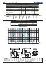
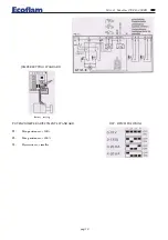
(LANDIS & STAEFA LGB 21/LGB 22) UP CYCLE

Thermostat

motor

Transformer

Gas valve

Flame

‡ 30 s

0,5 s

3 s

Air pressure switch

Necessary input signal

output signal of the device

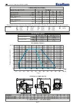
To calculate the burner’s working output, in kW, proceed as follows:

- Check at the meter the quantity of supplied litres and the duration, in seconds, of the
reading, then calculate the burner’s output through the following formula:

CALCULATION OF WORKING OUTPUT OF THE BURNER

   e   x f = kW

s

Litres of gas

Time in seconds

G20 = 34,02
G25 = 29,25
G30 = 116
G31 = 88  

f

+

-

0

1

2

3

4

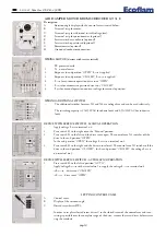
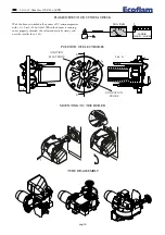
SETTING THE FIRING HEAD

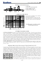
ADJUSTING THE AIR PRESSURE SWITCH

The air pressure switch must be adjusted so that an insufficient air flow does not allow
the CO value to exceed 1%  in volume. After having adjusted the gas flow and obtained
optimum combustion (CO

2

= 9.5 to 9.8% and a CO value of less than 75 ppm), the air

pressure switch must be adjusted. Remove the cover with the burner operating, cover the
air intake progressively with a piece of cardboard to obtain a value of CO

2

= 10.8 (G20-

G25)> 13 (G30-G31) and a CO value of less than 5,000 ppm. Adjust the air pressure
switch until the burner shuts down. Remove the cardboard from the air intake and start
up the burner again. Replace the cover.

ADJUSTING THE GAS PRESSURE SWITCH

Adjust the pressure switch to 50% of the rated pressure of the gas used.
RARED PRESSURE:

G 20 = 20 mbar     G 25 = 25 mbar   

G 30 = 29 mbar     G 31 = 37 mbar

0,4

0,6

0,9

3,0

1

,5

2,1

1,8

2,4

2,7

1,

2

A

B

2,5

5

10

15

50

2

5

35

30

40

45

20

C

D

Summary of Contents for MAX GAS 170 PR

Page 1: ...MAX GAS 170 PR MAX GAS 250 PR LB1681 29 01 2009 BRUCIATORI A GAS PROGRESSIVI BLOWN AIR GAS BURNERS...

Page 2: ...C I kcal Nm3 8 570 7 370 22 260 29 320 Modello Max Gas 170 Portata gas max 17 60 Nm3 h 20 47 Nm3 h 6 78 Nm3 h 5 14 Nm3 h min 5 53 Nm3 h 6 43 Nm3 h 2 13 Nm3 h 1 62 Nm3 h Modello Max Gas 250 Portata ga...

Page 3: ...amera di combustione kW d diametro camera di combustione L installazione deve essere fatta in confor mit alle disposizioni locali I bruciatori sono stati omologati in camere di combu stione secondo le...

Page 4: ...portata di funzionamento in kW del bruciatore procedere nel modo seguente Controllare al contatore la quantit di litri erogati e la durata in secondi della lettura quindi procedere al calcolo della p...

Page 5: ...Campo di guida pL 0 4 mbar fino a 100 mbar Campo pressione al bruciatore pBr 0 5 mbar fino a 100 mbar Montaggio linee ad impulsi 1 p e pressione gas in entrata 15 360 mbar 4 p Br pressione al bruciat...

Page 6: ...0 5A 250VAC a carico induttivo APPARECCHI CON INTERRUTTORE AUSILIARIO SERVIZIO A MANO Applicare tensione L A MANO al morsetto n 6 1 Posizionare l interruttore S2 sulla posizione a mano 2 Posizionare...

Page 7: ...on il bruciatore in funzione e regolato correttamente il valore letto dovr essere stabile e mai inferiore a 3 A CONTROLLO SISTEMA DI RILEVAZIONE FIAMMA REGOLAZIONE JUMPER STANDARD settato in fabbrica...

Page 8: ...B LB 1681 Max Gas 170 PR 250 PR pag 8 2 3 1 MONTAGGIO DEL BRUCIATORE POSIZIONI PER MANUTENZIONE POSIZIONE ELETTRODI 18 3 Sez A 3 1 0 5 0 5 A A 1 9 ELETTRODO DI RIVELAZIONE ELETTRODO DI ACCENSIONE...

Page 9: ...del gas aperto Che i sistemi di controllo siano regolarmente collegati Se tutte queste condizioni sono soddisfatte far partire il bruciatore premendo il pulsante di sblocco Controllare il ciclo del b...

Page 10: ...3 8 570 7 370 22 260 29 320 Model Max Gas 170 Gas flow rate max 17 60 Nm3 h 20 47 Nm3 h 6 78 Nm3 h 5 14 Nm3 h min 5 53 Nm3 h 6 43 Nm3 h 2 13 Nm3 h 1 62 Nm3 h Model Max Gas 250 Gas flow rate max 24 14...

Page 11: ...0 225 d 0 3 d 0 4 d 0 5 d 0 6 d 0 7 d 0 8 b a Lunghezza camera di combustione kW d diametro camera di combustione L installazione deve essere fatta in confor mit alle disposizioni locali The burners...

Page 12: ...kW proceed as follows Check at the meter the quantity of supplied litres and the duration in seconds of the reading then calculate the burner s output through the following formula CALCULATION OF WORK...

Page 13: ...test together with the burner Route pulse lines in such a way that no condensate can flow into the MBC VEF ADJUSTMENT The valve adjustment executed acting on the 2 screws V and N photo 2 Procedere com...

Page 14: ...C for ohmic loads and 0 5A 250VAC for inductive loads DEVICE WITH SERVICE SWITCH MANUAL OPERATION Apply voltage L MAN to terminal n 6 1 Press switch S2 to the right onto the Manual position 2 Press sw...

Page 15: ...1681 Max Gas 170 PR 250 PR B pag 15 JUMPER SETTING STANDARD factory setting DIP SWICH POSITIONS POTENZIOMETER ADJUSTMENTS STANDARD P1 Min position cw 100 P2 Max position cw 100 P3 Hysteresis cw small...

Page 16: ...a 0 50 or 0 100 A dial When the burner is running and is properly adjusted the value read must be steady and never be smaller than 3 A FLAME DETECTION SYSTEM CHECK POSITION OF ELECTRODES 18 3 Sez A 3...

Page 17: ...as pressure is correct and the gas cock open That the control systems are correctly connected If all these conditions are present start the burner by pressing the release button Check the burner cycle...

Page 18: ...RESSOSTATO GAS DI MINIMA SPGmin ELETTROVALVOLA GAS DI SICUREZZA YVGS ELETTROVALVOLA GAS DI PRIMA FIAMMA YVG1 TERMOSTATO DI SICUREZZA STS TERMOSTATO CALDAIA STC PRESSOSTATO ARIA SPA LAMPADA DI BLOCCO H...

Page 19: ...LB 1681 Max Gas 170 PR 250 PR B pag 19 Z 16 MAX GAS 170 PR MAX GAS 250 PR 25 28 29 30 24 22 23 20 21 27 26 17 18 19 11 15 12 1 4 5 9 3 MAX GAS 170 6 10 2 31 32 33 34 35 13 7 8 14 F IN D E R F IN D E R...

Page 20: ...2 6 19 CAVO DI ACCENSIONE TC BFE01401 5 BFE01401 5 TL BFE01401 9 BFE01401 9 20 ELETTRODO DI RIVELAZIONE BFE01078 BFE01078 21 ELETTRODO DI ACCENSIONE BFE01077 BFE01077 22 ASTINA REGOLAZIONE TESTA TC BF...

Page 21: ...E1102 7 TL E1102 6 E1102 6 19 IGNITION CABLE TC BFE01401 5 BFE01401 5 TL BFE01401 9 BFE01401 9 20 IONIZATION PROBE BFE01078 BFE01078 21 IGNITION ELECTRODE BFE01077 BFE01077 22 ROD TC BFA07016 001 BFA...

Page 22: ...B LB 1681 Max Gas 170 PR 250 PR pag 22...

Page 23: ...LB 1681 Max Gas 170 PR 250 PR B pag 23...

Page 24: ...coflam burners com societ soggetta alla direzione e al coordinamento della Merloni Termosanitari S p A via A Merloni 45 60044 Fabriano An CF 01026940427 BECOFLAM BRUCIATORI S p A reserves the right to...

Reviews: