


417101438_EMPII_E60.docx
- 97 -
Rev. 11-02.14
9.4
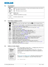
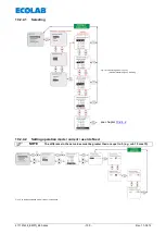
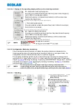
Key functions
Description
MENU/EXIT function entry and exiting of the menu levels (keep keys pressed down together)
(
) Modify set values upwards
(
) Modify set values downwards
Fig. 9.3
Menu/Exit
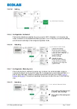
Start the pump
Stop the pump
Confirmation key (ENTER) for set values
Fig. 9.4
Start/Stop
Test function (endurance test)
Fig. 9.5
Testfunktion
9.5
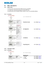
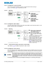
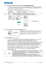
Description of display symbols
Display
Description
Pump’s operation mode: the top right indicator in the display
makes a full rotation with each
stroke.
Level report is active (flashing display = low level advance warning, display is permanently visible
= empty report), see
Installing the suction pipe with low-level advance warning and empty
Configuration / Low-level contact
Metering lock active, see
Installing the control via the metering lock or
Configuration / Metering lock
Fault report, see
Intern
Operation mode internal, see
MUL
Operation mode pulse multiplication, see
DIV
Operation mode pulse division, see
x..xx mA
Operation mode current x – xx mA, see
Operation mode / current
Charge
Operation mode batch see
xxx /min
Display strokes / min at Operation mode internal
xx %
Display % at Operation mode internal
x.xx l/h
Display l/h at Operation mode internal see
Display / setting operation mode internal
n = x
Display at operation mode pulse, see
Display / setting operation mode pulse
xx.x mA
Display at operation mode current, see
Display / operation mode current
f = xx.x %
Display of the current metering frequency in %
OFF
Pump is in operating state OFF (must be switched on)
E60+
Dongle box is connected, see
®
Serie B E60
Plus
E60++
Dongle box and OGM
PLUS
are connected, see
Installing the oval gear meter or
Configuration / Oval gear meter
Alarm
Alarm operation mode, see
9.6
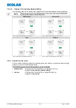
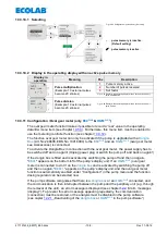
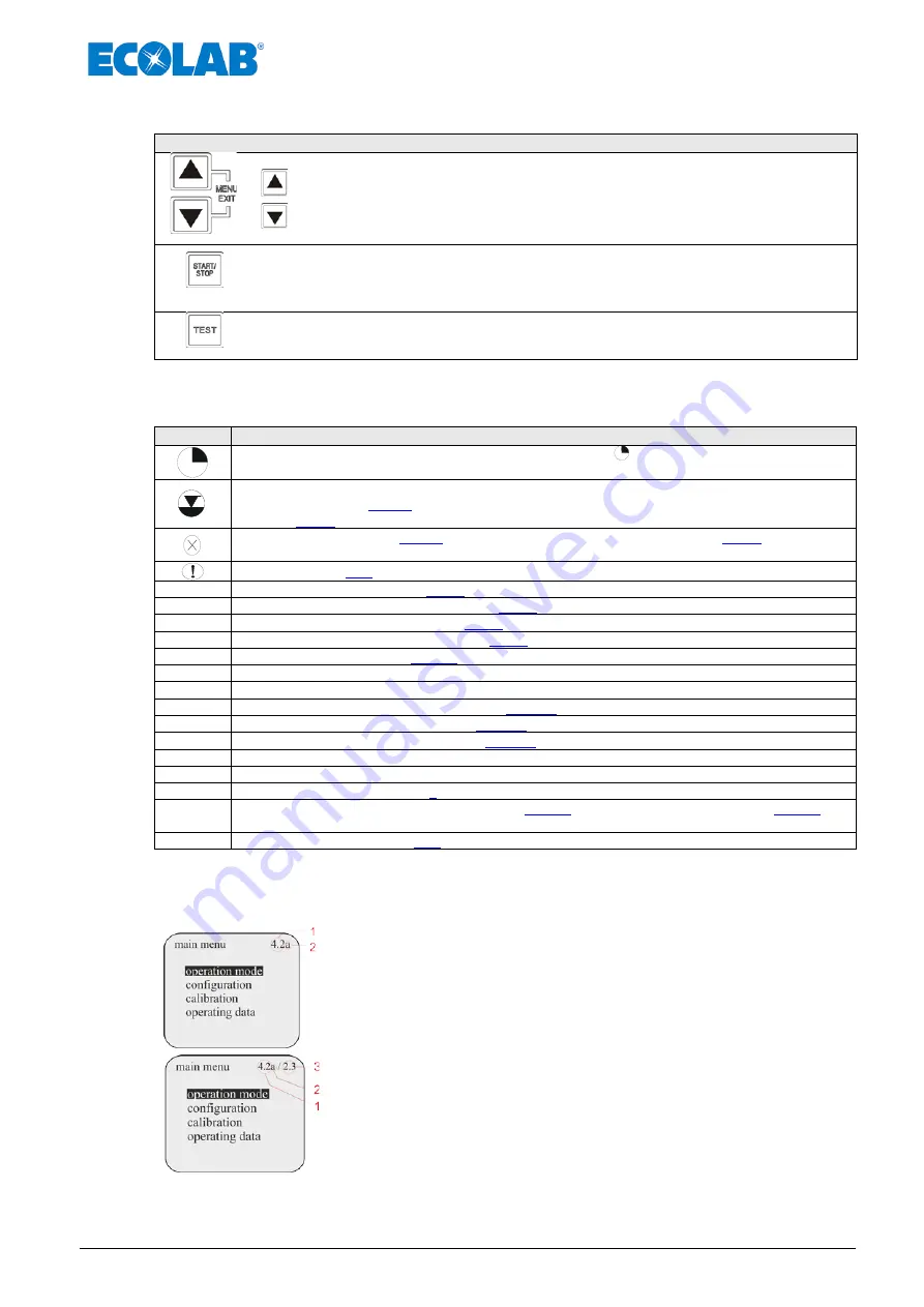
Software version display
The current software version (Pos.
1
) is displayed (Fig 9.6 & 9.7) in
the top right of the main menu screen
Lowercase letters after the software number (Pos.
2
) describe
internal software modifications that do not affect the operation of
the device.
Fig. 9.6
Software version display 1
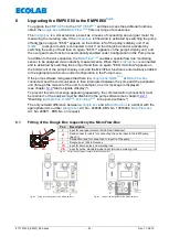
If a
Dongle box
or a
MicroFlow
PLUS
has been connected, the unit
version (Pos.
3
) is displayed to the right of the pump version.
Fig. 9.7
Software version display 1


