background image


417101438_EMPII_E60.docx 

- 66 - 

Rev. 11-02.14 


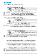
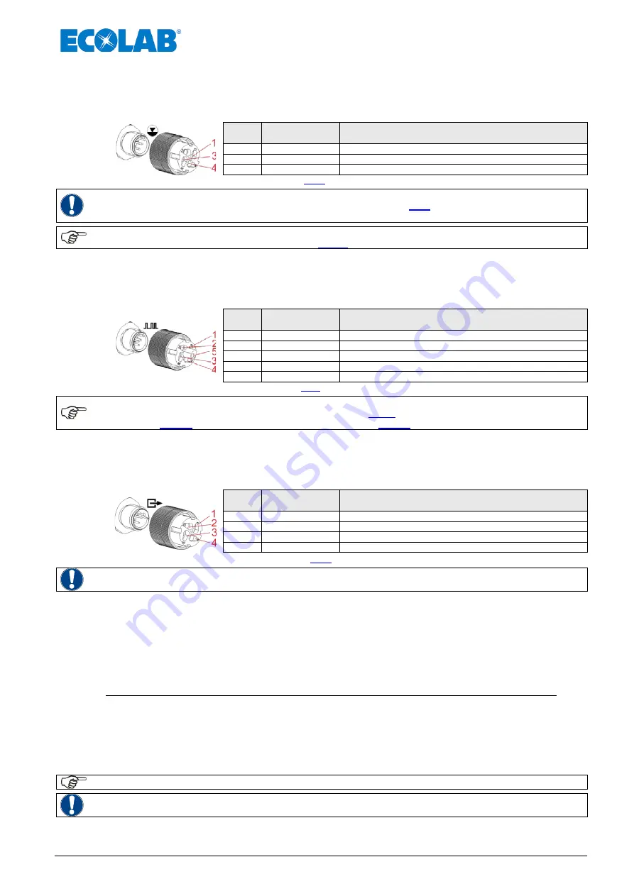
14.3.5  Anschlussstecker / Steuer Ein- und Ausgänge 

14.3.5.1 

Pinbelegung / Aderfarben Stecker I (3-polig) 

Anschluss Niveauvorwarnung bzw. Leermeldung


Abb. 14.6  Stecker I (3-polig)


Pos. 

Aderfarbe 

(Anschlusskabel) 

Bezeichnung 

braun 

Niveauvorwarnung 

blau 

Niveau- Leermeldung 

schwarz 

GND 

siehe auch Kapitel: 

7.2.2 

„Anschlussbelegung Steckplatz I (3-polig)“


ACHTUNG 

Falls die Leermeldung nicht benutzt wird, muss Kontakt 3/4 immer gebrückt werden! 
Die hierfür vorgesehene Schutzkappe (siehe Kapitel 

7.2.1

 „Ein-und Ausgänge“) stellt die 

Brücke zwischen den Kontakten her und muss in diesem Fall aufgesteckt sein.


HINWEIS 

Der Leer- und Reservemeldeeingang kann im Menü “Konfiguration / Niveaukontakt“ 
invertiert werden. (siehe Kapitel


10.3.8)


14.3.5.2 

Pinbelegung / Aderfarben Stecker II (5-polig) 

Anschluss Impuls- / Normsignaleingang und Dosiersperre


Abb. 14.7  Stecker II (5-polig)


Pos. 

Aderfarbe 

(Anschlusskabel) 

Bezeichnung 

braun 

Ausgang 5 V, DC 

weiß 

Impulseingang 

blau 

Eingang Dosiersperre 

schwarz 

GND 

grau 

Eingang Normsignal 0/4 … 20 mA 

siehe auch Kapitel 

7.2.3 

„Anschlussbelegung Steckplatz II (5-polig)“ 


HINWEIS 

Der Dosiersperreneingang ist nur aktiv, wenn er zuvor im Menü “Konfiguration / 
Dosiersperre eingestellt wurde (siehe Kapitel


10.3.7

). Die Funktion Charge (siehe Kapitel


10.3.15

) und Dosierüberwachung (siehe Kapitel


10.3.13

) muss ebenfalls konfiguriert werden 


14.3.5.3 

Pinbelegung / Aderfarben Stecker III (4-polig) 

Anschluss Leermelde-, Störmelde-, Hubsignalausgang:


Abb. 14.8  Stecker III (4-polig)


Pos. 

Aderfarbe 

(Anschlusskabel) 

Bezeichnung 

braun 

Ausgang Niveauvorwarnung, Niveau- Leermeldung, Störung (+) 

weiß 

Ausgang Niveauvorwarnung, Niveau- Leermeldung, Störung (-) 

blau 

Ausgang Hubsignal (+) 

schwarz 

Ausgang Hubsignal (-) 

siehe auch Kapitel 

7.2.4

 „Anschlussbelegung Steckplatz III (4-polig)“


ACHTUNG 

Bei Anschluss von 115V/230 V an Kontakt 

1

+

2

 (Alarmausgang) ist ein gleichzeitiges Nutzen 

von Kontakt 

3

+

4

 (Hubsignalausgang) generell nicht erlaubt 


14.4 

Dosierleistungen 

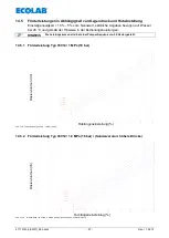
Die reproduzierbare Dosiergenauigkeit beträgt ca. ± 3 % bei minimal 30 % Hublänge und 
gleich bleibenden Verhältnissen. Durch die Charakteristik der Pumpe kann es bis zum 
Erreichen der Betriebstemperatur zu höheren Leistungen kommen. 

Unter Beachtung folgender Punkte kann eine genaue Dosierung erreicht werden: 

  Alle Dosierleistungsangaben sind bezogen auf Messungen mit Wasser bei 20 °C sowie 

konstanter Versorgungsspannung und betriebswarmen Zustand der Dosierpumpe. 

  b  Liegt auf der Saugseite ein Vordruck an, muss der Differenzdruck zwischen Saug- und 

Druckseite mindestens 0,1 MPa (1 bar) betragen. Die anstehende Wassersäule auf die 
Dosierpumpe muss durch eine entsprechende Ventilanordnung abgesichert werden. 


HINWEIS 

Ein Druckhalteventil oder ein Dosierventil ist kein absolut schließendes Absperrorgan. 


ACHTUNG 

Dosierhubverstellung nur bei laufender Pumpe, wenn die Hubeinstellschraube entlastet ist.


Summary of Contents for Elados EMP II E60

Page 1: ...14 Betriebsanleitung Operating Instruction Mode d emploi Elados EMP II E60 und and et Elados EMP II E60PLUS Abb 0 1 EMP II E 60 Abb 0 2 EMP II E 60PLUS mit Dongle Box EMP II E 60 EMP II E 60PLUS mit D...

Page 2: ...on Chargenfunktion 15 7 2 3 5 Installation Dosier berwachung 16 7 2 4 Anschlussbelegung Steckplatz III 4 polig Ausgang f r Alarm und Hubsignal 16 7 2 4 1 Installation Niveau bzw St rmeldeausgang 17 7...

Page 3: ...GM PLUS 36 10 3 11 1 Ausw hlen 37 10 3 12 Konfiguration Dosierregler nur E60PLUS OGM PLUS 37 10 3 12 1 Ausw hlen 37 10 3 12 2 Displayanzeige in der Betriebsebene bei aktiviertem Dosierregler 38 10 3 1...

Page 4: ...sel 60 14 1 1 Pumpenschl ssel 1 60 14 1 2 Pumpenschl ssel 2 61 14 1 3 Pumpenschl sseldefinition 62 14 2 Abmessungen 63 14 2 1 Typ V3014 V3025 00043 00048 00072 und Typ 00112 63 14 2 2 Typ 00240 63 14...

Page 5: ...lnummern und werden konzernintern verwendet 1 2 Transportsch den VORSICHT Wird beim Auspacken ein Transportschaden festgestellt darf die Pumpe nicht installiert werden ACHTUNG 1 3 Gew hrleistungsumfan...

Page 6: ...edienungsanweisungen Arbeitsanweisungen vorgeschriebenen Arbeitsabl ufen und dergleichen zur Besch digung des Ger tes f hren kann WICHTIG wird benutzt wenn auf eine besondere Aufmerksamkeit im Umgang...

Page 7: ...ignaleingang Abb 3 2 Lieferumfang Anschlussstecker Anschlussteile f r Schlauch 4 6 6 8 6 12 ID AD mm Abb 3 3 Lieferumfang Anschlusssteile Montageskizze f r Schlauchanschl sse Beipack Steckerbelegungsp...

Page 8: ...die Verwendung einer Sauglanze mit Leermeldeeinrichtung und Schmutzf nger aus unserem Zubeh rprogramm dringend empfohlen Die Leermeldeeinrichtung schaltet bei Unterschreitung eines bestimmten Niveaus...

Page 9: ...LUS Abb 5 5 Ausf hrung EMP II E 60 und EMP II E60 PLUS Pos Bezeichnung 1 Drehknopf f r Hubl ngeneinstellung 2 Menu Exit Pfeil nach oben Taste 3 Menu Exit Pfeil nach unten Taste 4 Start Stop Taste Ente...

Page 10: ...bersteigen Die Einbaulage des Ger tes muss waagrecht sein Die Pumpe ist an den daf r vorgesehenen Bohrungen fest mit der Konsole bzw dem Beh lter zu verschrauben Bohrungsabstand siehe Kapitel 14 2 Ab...

Page 11: ...ierleitung ein entsprechendes Sicherheits berstr mventil Pos 3 zu installieren Die berstr mleitung dieses Ventils sollte drucklos in den Beh lter zur ckgef hrt werden ACHTUNG Die berstr mleitung darf...

Page 12: ...rheberns des Entnahmebeh lters besteht Pos Bezeichnung 1 berstr mventil 2 Impfventil Dosierventil Abb 7 4 Hydraulische Installation Installationsbeispiele 4 Saugleitungen sind so kurz wie m glich zu h...

Page 13: ...Pos 5 und 11 in Ventilnut legen und berwurfmutter festziehen Die Sauglanze ins Liefergebinde stellen 7 2 Elektrische Installation 7 2 1 Ein und Ausg nge Abb 7 9 Elektrische Installation Ein und Ausg n...

Page 14: ...nstallation Sauglanze mit Niveauvorwarnung und Leermeldung 7 2 3 Anschluss Steckplatz II 5 polig Eingang f r Impuls Normsignal Dosiersperre Charge und Dosier berwachung Abb 7 12 Steckplatz II 5 polig...

Page 15: ...genfunktion muss zuerst im Men aktiviert werden Au erdem muss ausgew hlt werden ob die Pins 2 4 Eingang Impuls oder 3 4 Eingang Dosiersperre f r den Startimpuls der Chargendosierung genutzt werden sol...

Page 16: ...ang Dosier berwachung mit potentialfreiem Kontakt bei Wahl Eingang Dosiersperre in Konfiguration Dosier berwachung siehe Kapitel 10 3 13 PIN Belegung 3 Schalteingang 4 GND 1 3 4 Eingang Dosier berwach...

Page 17: ...bei 24 V DC 3 4 Hubsignalausgang Mit jedem Hub der Pumpe wird der Schaltausgang einmal geschlossen Schaltausgang potentialfreier Transistorausgang Belastung 24 V DC 300 mA PIN Belegung 3 Schaltausgang...

Page 18: ...Alarmrelais hat nicht angezogen Schlie erfunktion Standardeinstellung Kontakt geschlossen Kontakt offen Kontakt offen ffnerfunktion Kontakt offen Kontakt geschlossen Kontakt geschlossen fail safe Fun...

Page 19: ...h die Funktion MicroFlow mit dem entsprechenden Untermen freigeschaltet Hat die Pumpensoftware eine angeschlossene Dongle Box einen OGM PLUS oder eine MicroFlow Box einmal erkannt und die Kommunikatio...

Page 20: ...Pos VIII der Dongle Box bzw der MicroFlow Box angeschlossen werden 8 2 Anschlussbelegung der Steckpl tze 8 2 1 Anschlussbelegung Steckplatz V 5 polig Dongle Box Pin Aderfarbe Anschlusskabel Belegung...

Page 21: ...ingang f r Chargenimpuls und Dosiersperre Pin Aderfarbe Anschlusskabel Belegung 1 braun Ausgang 5 V DC belastbar mit max 50 mA 2 wei Eingang Chargendosierung 3 blau Eingang Dosiersperre 4 schwarz GND...

Page 22: ...e siehe Kapitel 10 3 15 PIN Belegung 3 Schalteingang 4 GND 1 3 4 Eingang Chargendosierung mit elektronischem Schalter NPN bei Wahl Eingang Dosiersperre in Konfiguration Charge siehe Kapitel 10 3 15 PI...

Page 23: ...iem Kontakt PIN Belegung 2 Schalteingang 4 GND 1 2 4 Impulseingang mit elektronischem Schalter NPN PIN Belegung 1 5 V DC 2 Schalteingang 4 GND Die minimale Impuls bzw Pausendauer betr gt 15 ms Abb 8 1...

Page 24: ...sierleistung mechanisch HINWEIS F r eine genaue Ermittlung der Dosierleistung muss die Pumpe kalibriert werden siehe Kapitel 10 4 Kalibrierung 9 3 Entl ftung der Dosierpumpe ACHTUNG Besondere Vorsicht...

Page 25: ...Kapitel 10 2 4 Betriebsart Strom Charge Betriebsart Charge siehe Kapitel 10 3 15 Konfiguration Charge xxx min Anzeige H be min bei Betriebsart Intern xx Anzeige bei Betriebsart Intern x xx l h Anzeig...

Page 26: ...der Pumpe rotiert die Anzeige oben rechts im Display um 1 Umdrehung 9 7 2 Grundeinstellungen in der Konfiguration In der Konfiguration sind werksseitig folgende Einstellungen festgelegt Abb 9 9 Grund...

Page 27: ...aliges gleichzeitiges Dr cken der und Tasten erfolgt die R ckkehr in die Betriebsebene 10 1 1 bersicht Abb 10 1 Men beschreibung bersicht Betriebsart siehe Kapitel 10 2 Konfiguration siehe Kapitel 10...

Page 28: ...estellte Dosiergeschwindigkeit und somit Dosiermenge wird in H be min angezeigt Standardeinstellung Prozent Die eingestellte Dosiergeschwindigkeit und somit Dosiermenge wird in Prozent angezeigt Liter...

Page 29: ...bb 10 5 Displayanzeige in der Betriebsebene Einstellen Prozent Liter Gallonen Abb 10 6 Displayanzeige in der Betriebsebene Einstellen Liter Abb 10 7 Displayanzeige in der Betriebsebene Einstellen Gall...

Page 30: ...halb von 10 Sekunden durch Dr cken der START STOP Taste best tigt wird bleibt der zuvor eingestellte laufende Wert erhalten 10 2 4 Betriebsart Strom Extern Normsignal Bei Betriebsart Strom arbeitet di...

Page 31: ...10 11 Betriebsart Strom Extern Normsignal Ausw hlen Siehe Kapitel 10 2 4 2 10 2 4 2 Einstellen Betriebsart Strom beliebig HINWEIS Die Differenz der eingestellten Werte muss gr er oder gleich 5 sein z...

Page 32: ...lradz hler 10 3 11 Dosierregler 10 3 12 Dosier berwachung 10 3 13 MicroFlow 10 3 14 Dieser Men punkt erscheint nur in Verbindung mit der als Zubeh r erh ltlichen Dosier berwachung MicroFlow und ersetz...

Page 33: ...3 4 1 Ausw hlen Abb 10 17 Konfiguration Einheit Ausw hlen Standardeinstellung Liter 10 3 5 Konfiguration Code In dieser Einstellung kann eine Zahlenkombination zur Sicherung der Einstellwerte gegen b...

Page 34: ...ebszustand OFF Standby bei V 4 0 Standardeinstellung Autostart ist aktiv Die Pumpe geht bei Anlegen der Netzspannung in den aktuell eingestellten Betriebszustand 10 3 7 Konfiguration Dosiersperre Bei...

Page 35: ...t des Alarmausgangs Relais geschlossen Schlie erfunktion Standardeinstellung oder offen ffnerfunktion sein soll siehe Kapitel 7 2 4 3 Umstellung Funktionsweise Alarmrelais Kontakt Abb 10 23 Konfigurat...

Page 36: ...ion Ovalradz hler wird aktiv wenn die Pumpe durch eine Dongle Box Art Nr 248606 EBS Nr 10016094 zur E60 PLUS erweitert und ein OGM PLUS Ovalradz hler siehe Zubeh r angeschlossen wurde Ist die Dongle B...

Page 37: ...r Pumpe m glich ist empfiehlt es sich die Dosiermengen Vorgabe auf h chstens 80 90 der maximal m glichen Dosierfrequenz einzustellen Dadurch hat der Dosierregler nach oben hin Reserven um auf negative...

Page 38: ...0 3 13 Konfiguration Dosier berwachung Bei aktivierter Dosier berwachung erfolgt ein Vergleich zwischen den get tigten Pumpenh ben und den eingehenden Impulsen einer externen Dosier berwachung z B Ova...

Page 39: ...er berwachung Abweichung nur bei E60PLUS OGM bzw OGMPLUS Bei Abweichung wird eine Toleranz in eingestellt Die vom Ovalradz hler eingehende tats chliche Impulsrate innerhalb des zu berwachenden Pumpeni...

Page 40: ...einem Durchfluss sensor Art Nr 288413 EBS Nr 10005481 einem Anschlusskabel Art Nr 284412 EBS Nr auf Anfrage und einer Auswertebox Art Nr 248611 EBS Nr auf Anfrage Nach Anschluss der MicroFlow Box sie...

Page 41: ...5 Dosierverz gerung 10 3 14 6 Kalibrierung 10 3 14 7 10 3 14 2 MicroFlowPLUS Pumpe stoppen Abb 10 41 Konfiguration MicroFlow PLUS Pumpe stoppen Mit Pumpe stoppen wird eingestellt ob die Pumpe bei Alar...

Page 42: ...ben Einstellbereich 0 100 Standardeinstellung 40 10 3 14 5 MicroFlowPLUS Dosierpause Bei Umgang mit Medien die zur Ausgasung neigen bilden sich nach l ngeren Stillstandszeiten Gaseinschl sse im System...

Page 43: ...r Erstinstallation oder bei einem Produktwechsel neu kalibriert WICHTIG W hrend der Kalibrierung muss die Pumpe mit der gew nschten Einstellung laufen und das Dosiermedium muss blasenfrei durch den Me...

Page 44: ...tellung Charge ist aktiv Bei aktivierter Chargendosierung erscheinen folgende Punkte im Untermen Men punkt siehe Kapitel Menge 10 3 15 2 Eingang 10 3 15 3 10 3 15 2 Charge Menge Mit Menge wird die gew...

Page 45: ...eparater Eingang zur Verf gung Abb 10 49 Konfiguration Charge Eingang nur bei E60 OHNE Dongle Box Standardeinstellung Dosiersperre 10 3 15 4 Displayanzeige in der Betriebsebene Pos Bezeichnung 1 Betri...

Page 46: ...t Sollte w hrend dieser Zeit eine Dosieranforderung kommen wird diese abgearbeitet und die DegasPLUS Pausenzeit wird zur ckgesetzt und neu gestartet Einstellbereich Stunden 00 23 Minuten 00 59 ges 00...

Page 47: ...r ndert werden Die Kalibrierung der Dosierpumpe ist nur f r die aktuell eingestellte Hubl ngeneinstellung g ltig Nach Ver nderung der Hubl nge ist die Kalibrierung erneut durchzuf hren 10 4 2 2 Kalibr...

Page 48: ...ubl nge ist die Kalibrierung erneut durchzuf hren 10 4 3 2 Kalibrierung Starten Abb 10 58 Kalibrierung Starten Zu Die Pumpe l uft 122 H be lang ca 1 min Die H be werden von 122 r ckw rts bis 0 gez hlt...

Page 49: ...aten Mit den in der Tabelle angegebenen Kalibrierwerten wird der Elektronik der Pumpe die jeweilige Pumpenleistung in l h zugeordnet Beispiel Ein eingegebener Wert von 23 3 ml ergibt eine Pumpenleistu...

Page 50: ...5 2 1 Ausw hlen Anzeigen L schen Abb 10 63 Betriebsdaten Ausw hlen Anzeigen L schen 10 5 3 Betriebskosten Liter Hier wird die dosierte Menge in Liter seit Erstinbetriebnahme bzw seit der letzten R ck...

Page 51: ...e ber den Impulseingang der Pumpe Stecker II Pin 3 4 siehe Kapitel 7 2 3 Anschlussbelegung Stecker II eingegangene Anzahl an Impulsen seit Erstinbetriebnahme bzw seit der letzten R cksetzung angezeigt...

Page 52: ...s von Saug und Druckventil siehe Kapitel 11 1 Austausch von Saug R cklauf und Druckventil auf Verschmutzung und Dichtigkeit des Ablaufanschlusses siehe Kapitel 5 1 EMP II E60 am Pumpenkopf Membranbruc...

Page 53: ...st die Flie richtung mittels eines eingepr gten Pfeils markiert Beim Einbau ist unbedingt darauf zu achten dass die Ventile der Flie richtung entsprechend eingebaut werden Abb 11 4 Wartung Dosierventi...

Page 54: ...b 11 6 Pumpenkopfschrauben handfest eindrehen Pumpenkopfschrauben ber Kreuz anziehen HINWEIS Anzugsmoment der Dosierkopfschrauben 3 4 Nm ACHTUNG Dosierkopfschrauben Anzugsmoment nach 24 Stunden berpr...

Page 55: ...Dauerdosierung Steckverbindung von Getriebe zur Platine unterbrochen Pumpe einschicken Platine defekt Optischer Sensor verschmutzt Optischen Sensoranschluss berpr fen Abb 12 8 Betriebsst rungen Alarmm...

Page 56: ...wechseln Falsche Spannung Netzspannung berpr fen Pumpe saugt trotz Entl ftung und max Hub nicht an Ablagerungen Verkleben Austrocknen der Ventile ber Saugleitung den Dosierkopf durchsp len evtl Venti...

Page 57: ...7 Entl ftungsschraube PVDF VITON B 243077 10003132 Entl ftungsschraube PVDF EPDM 243091 auf Anfrage 8 Faltenbalg 34800132 10003134 9 Klarsichtdeckel bedruckt 34800120 10015884 10a Blindstecker Leermel...

Page 58: ...459 10004488 00043 00048 PVEPKE 248488 auf Anfrage 00072 PVEPKE 248489 auf Anfrage 00112 PVEPKE 248490 auf Anfrage 1 Pumpentyp Pumpenleistung V3014 1 4 l h V3025 2 5 l h 00043 00048 4 3 4 8 l h 00072...

Page 59: ...hnitt 34004207 auf Anfrage 10 Faltenbalg 34800132 10003134 11 Klarsichtdeckel bedruckt 34800120 10015884 12 Netzkabel EMP KKS II E60 Schuko 2m 34860001 auf Anfrage 13a Blindstecker Leermeldeeingang 24...

Page 60: ...a 2 bar bei 24 l h 0 16 MPa 04 0 4 MPa 4 bar bei 4 8 l h 0 32 Mpa 05 0 5 MPa 5 bar bei 11 2 l h 0 40 MPa 06 0 6 MPa 6 bar bei 7 2 l h 0 48 MPa 10 1 MPa 10 bar bei 1 4 2 5 4 3 7 2 l h 0 8 MPa Sonderver...

Page 61: ...nschluss PV PVDF Standard PP PP 14 Elektrische Hubverstellung 99 ohne elektrische Hubverstellung 15 Membranbrucherkennung 99 ohne Membranbrucherkennung 16 Geh useversion 01 Standardgeh use Andere Spez...

Page 62: ...lsdivision n eingehende Impulse 1 Dosierhub Normsignalbetrieb Ansteuerung ber externes Normsignal 0 4 20 mA bzw 20 0 4 mA Chargenbetrieb ausgel st durch einen externen Freigabeimpuls wird eine vorher...

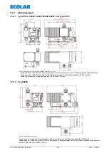
Page 63: ...ildet 246 6 mm L ngenmass bei Typ 00072 und 00112 mit BLDC Motor erkennbar an Spannungsangabe 100 240V auf dem Typenschild identisch mit dem der Typen 00014 bis 00043 218 mm 14 2 2 Typ 00240 Abb 14 2...

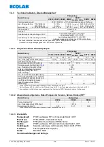
Page 64: ...60 Hz 0 19 0 34 0 65 0 57 0 98 1 5 3 28 Dosiergenauigkeit siehe Kapitel 14 6 3 max f rderbare Viskosit t mPas 200 zul ssige Umgebungstemperatur 5 40 C Saugh he mWs bei 100 Hubeinstellung 2 max Vordru...

Page 65: ...xterne Versorgung 1 braun 4 schwarz potentialfreier Kontakt Achtung Keine externe Spannung anschlie en Versorgung f r externe Ger te Ausgang 5V DC max 50 mA 14 3 4 3 Steckplatz III Ausg nge Belegung E...

Page 66: ...tel 10 3 13 muss ebenfalls konfiguriert werden 14 3 5 3 Pinbelegung Aderfarben Stecker III 4 polig Anschluss Leermelde St rmelde Hubsignalausgang Abb 14 8 Stecker III 4 polig Pos Aderfarbe Anschlusska...

Page 67: ...edienungsanleitungen HINWEIS Die Leistungskurven sind bei einer Pumpenfrequenz von 50 Hz dargestellt 14 5 1 F rderleistung Typ V3014 1 MPa 10 bar Dosiervolumen l h Hubl ngeneinstellung Abb 14 9 F rder...

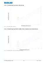
Page 68: ...bar Dosiervolumen l h Hubl ngeneinstellung Abb 14 11 F rderleistung Typ V3025 1 MPa 10 bar 14 5 4 F rderleistung Typ V3025 1 6 MPa 16 bar Sonderversion h here Dr cke Dosiervolumen l h Hubl ngeneinstel...

Page 69: ...bar Dosiervolumen l h Hubl ngeneinstellung Abb 14 13 F rderleistung Typ 00043 1 MPa 10 bar 14 5 6 F rderleistung Typ 00043 1 6 MPa 16 bar Sonderversion h here Dr cke Dosiervolumen l h Hubl ngeneinstel...

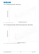
Page 70: ...leistung Typ 00048 0 4 MPa 4 bar Dosiervolumen l h Hubl ngeneinstellung Abb 14 15 F rderleistung Typ 00048 0 4 MPa 4 bar 14 5 8 F rderleistung Typ 00072 0 6 MPa 6 bar Dosiervolumen l h Hubl ngeneinste...

Page 71: ...leistung Typ 00072 1 MPa 10 bar Dosiervolumen l h Hubl ngeneinstellung Abb 14 17 F rderleistung Typ 00072 1 MPa 10 bar 14 5 10 F rderleistung Typ 00112 0 5 MPa 5 bar Dosiervolumen l h Hubl ngeneinstel...

Page 72: ...417101438_EMPII_E60 docx 72 Rev 11 02 14 14 5 11 F rderleistung Typ 00240 0 2 MPa 2 bar Dosiervolumen l h Hubl ngeneinstellung Abb 14 19 F rderleistung Typ 00240 0 2 MPa 2 bar...

Page 73: ...417101438_EMPII_E60 docx 73 Rev 11 02 14 15 Konformit tserkl rung...

Page 74: ...2 3 5 Installing the metering monitoring 88 7 2 4 Connector assignments of slot III 4 terminal output for alarm and stroke signal 88 7 2 4 1 Installing the alarm or fault report output 89 7 2 4 2 Inst...

Page 75: ...PLUS OGM PLUS 108 10 3 11 1 Selecting 109 10 3 12 Configuration Metering controller only E60PLUS OGMPLUS 109 10 3 12 1 Selecting 109 10 3 12 2 Display in the operating display with an active metering...

Page 76: ...2 14 1 1 Pump key 1 132 14 1 2 Pump key 2 133 14 1 3 Pump key definition 134 14 2 Dimensions 135 14 2 1 Type V3014 V3025 00043 00048 00072 and type 00112 135 14 2 2 Type 00240 135 14 3 Technical speci...

Page 77: ...only concern internal 1 2 Transport damage CAUTION If there is discovered a transport damage while unpacking the pump it must not be installed WARNING 1 3 Warranty coverage Operational safety reliabi...

Page 78: ...compliance or non compliance with the operating instructions work instructions prescribed working routines et cetera may result in damage to the equipment IMPORTANT Used when particular attention is...

Page 79: ...gnal input Fig 3 2 Delivery scope 5 terminal connector Adapters for tube 4 6 6 8 6 12 ID AD mm Fig 3 3 Delivery scope adapters Assembly sketch for tube connections accessory Connector assignment plan...

Page 80: ...rotect the metering device the use of a suction pipe with an empty reporting device and dirt arrestor available from our range of accessories is highly recommended The empty reporting device switches...

Page 81: ...EMP II E60PLUS Fig 5 5 Version EMP II E 60 and EMP II E60 PLUS Pos Description 1 Control knob for setting the stroke length 2 Menu Exit up arrow key 3 Menu Exit down arrow key 4 Start Stop key Enter...

Page 82: ...vice must be horizontal The pump must be securely screwed to the bracket or the container using the drill holes provided for information on the drill hole gap see chapter 14 2 Dimensions 6 1 Mounting...

Page 83: ...nce of inadmissibly high pressures in the metering line an appropriate safety overflow valve Pos 3 The by pass pipe of this valve should be led back pressure free into the container WARNING The overfl...

Page 84: ...of the discharge container being siphoned empty Pos Description 1 Overflow valve 2 Injector valve Metering valve Fig 7 4 Hydraulic installation installation examples 4 The suction pipes must be kept a...

Page 85: ...ighten the union nut Place the suction pipe in the delivery bundle 7 2 Electrical installation 7 2 1 Inputs and outputs Fig 7 9 Electrical installation Inputs and outputs The inputs and outputs in are...

Page 86: ...ith low level advance earning and empty report 7 2 3 Connector assignment of slot II 5 terminal input for pulse signal standard signal metering lock batch and metering monitoring Fig 7 12 slot II 5 te...

Page 87: ...atch function NOTE The batch function must be activated in menu first The selection must also be made of whether the pins 2 4 input pulse or 3 4 input metering lock should be used for the batch meteri...

Page 88: ...ct with selection input metering lock at configuration metering monitoring see chapter 10 3 13 PIN Assignment 3 Relay input 4 GND 1 3 4 Input metering monitoring function with electronic switch NPN wi...

Page 89: ...signal output at 24 V DC 3 4 Stroke signal output The contact is closed once with each stroke of the pump Relay output potential free transistor output load 24 V DC 300 mA PIN Assignment 3 Relay outpu...

Page 90: ...Default setting contact closed contact open contact open Opening function contact open contact closed contact closed fail safe function safe in the event of failure 7 2 5 Connector assignments of slo...

Page 91: ...te sub menu under Configuration in the Pump menu If the pump software recognises that there is a dongle box OGM PLUS or MicroFlow box connected and the communication is then interrupted between the pu...

Page 92: ...2 Connector assignments of the slots 8 2 1 Connector assignments of slot V 5 terminal Dongle box Pin Conductor coloring cable connection Assignment 1 brown Supply for oval gear meter 5 V DC load with...

Page 93: ...for batch pulse and metering lock Pin Conductor coloring cable connection Assignment 1 brown Output 5 V DC load with max 50 mA 2 white Input batch metering 3 blue Input metering lock 4 black GND 5 gre...

Page 94: ...ation batch see chapter 10 3 15 PIN Assignment 3 Relay input 4 GND 1 3 4 Input batch metering with electronic switch NPN with selection input metering lock at configuration batch see chapter 10 3 15 P...

Page 95: ...otential free contact PIN Assignment 2 Relay input 4 GND 1 2 4 Pulse input with electronic switch NPN PIN Assignment 1 5 V DC 2 Relay input 4 GND The minimum pulse or pause time is 15 ms Fig 8 12 Inst...

Page 96: ...ering output mechanical NOTE The capacity of the pump must be calibrated in order to determine the metering capacity precisely see chapter 10 4 Calibration 9 3 Venting the metering pump WARNING Partic...

Page 97: ...xx mA Operation mode current x xx mA see 10 2 4 Operation mode current Charge Operation mode batch see 10 3 15 Configuration Batch xxx min Display strokes min at Operation mode internal xx Display at...

Page 98: ...OTE With each stroke of the pump the indicator in the upper right of the display rotates 1 turn 9 7 2 Basic settings in the configuration The following factory settings are defined in the configuratio...

Page 99: ...ly press the and keys again to return to the operating display 10 1 1 Overview Fig 10 1 Menu description Overview Operation mode see chapter 10 2 Configuration see chapter 10 3 Calibration see chapter...

Page 100: ...The configured metering speed and thus the metering rate is displayed in strokes min Default setting Percent The configured metering speed and thus the metering rate is displayed as a percentage Lite...

Page 101: ...s Fig 10 5 Display inthe operating display Setting Percent Liter Gallons Fig 10 6 Display inthe operating display Setting Liter Fig 10 7 Display inthe operating display Setting Gallons 10 2 3 Operatio...

Page 102: ...ey the system reverts to the previously set running value 10 2 4 Operation mode current external standard signal In the current operation mode the pump functions on the basis of an incoming standard s...

Page 103: ...rating mode current external standard signal Selecting see chapter 10 2 4 2 10 2 4 2 Setting operation mode current user defined NOTE The difference in the set values must be greater than or equal to...

Page 104: ...meter 10 3 11 Metering controller 10 3 12 Metering monitoring 10 3 13 MicroFlow 10 3 14 This menu item only appears in conjunction with the MicroFlow metering monitor which is available as an accesso...

Page 105: ...85 litres 10 3 4 1 Selecting Fig 10 17 Configuration Unit Selecting Default setting litre 10 3 5 Configuration Code With this setting a four digit number combination can be assigned to secure the sett...

Page 106: ...4 0 operating state Default setting autostart is active When the mains voltage is connected the pump starts functioning in the configured operation state 10 3 7 Configuration Metering lock If the mete...

Page 107: ...lay contact is closed closing function on default setting when the relay is pulled in or open opening function see chapter 7 2 4 3 Hardware migration for alarm contact conversion from alarm relay mode...

Page 108: ...48606 EBS No 10016094 to the E60PLUS and an OGM PLUS oval gear meter see Accessories is connected To activate the Dongle Box in connection with the oval gear meter the power supply has to be switched...

Page 109: ...performance limitations of the pump setting the dosage quantities higher than 80 or 90 of the maximum possible metering frequency is not recommended This will ensure that the metering controller reta...

Page 110: ...OGMPLUS mounted 10 3 13 Configuration Metering monitoring If the metering monitoring function is enabled the pump strokes are compared to the incoming pulses using a connected external metering monit...

Page 111: ...0 100 Default setting 10 10 3 13 4 Metering monitoring Deviation only at E60PLUS OGM or OGMPLUS A tolerance in is set under deviation The actual incoming pulse rate recorded by the oval gear meter wi...

Page 112: ...r monitoring the dosing rate It consists of a flow rate sensor Art No 288413 EBS No 10005481 a connecting cable Art No 284412 EBS No on request and an analysis box Art No 248611 EBS No on request Once...

Page 113: ...14 6 Calibration 10 3 14 7 10 3 14 2 MicroFlowPLUS Stop pump Fig 10 41 Configuration MicroFlow PLUS Stop pump The stop pump function is used to set whether or not the pump stops if a metering monitor...

Page 114: ...d Setting range 0 100 Default setting 40 10 3 14 5 MicroFlowPLUS Metering break When handling media with a tendency to emit gas gas bubbles form in the system after extended downtimes resulting in cor...

Page 115: ...l installation or when changing the product IMPORTANT The pump must be running and the metering medium must flow through the transducers without any bubbles before starting the calibration process On...

Page 116: ...ng Batch is active If batch metering is active the following items appear in the submenu Menu item see chapter Quantity 10 3 15 2 Input 10 3 15 3 10 3 15 2 Batch Quantity Quantity is used to establish...

Page 117: ...tion Batch Input only at E60 WITHOUT Dongle box Default setting Metering lock 10 3 15 4 Display in the operating display Pos Description 1 Operation mode 2 Quantity remaining to be metered 3 Strokes r...

Page 118: ...nder degas break If a metering request is submitted during this period this is processed and the DegasPLUS break time is reset and restarted Setting range hours 00 23 minutes 00 59 total 00 01 23 59h...

Page 119: ...position The calibration of the metering pump is only valid for the currently set stroke length setting After changing the stroke length the calibration must be performed again 10 4 2 2 Calibration S...

Page 120: ...ging the stroke length the calibration must be performed again 10 4 3 2 Calibration Start Fig 10 58 Calibration Start to The pump runs 122 strokes ca 1 min The strokes are counted down from 122 to 0 T...

Page 121: ...The pump capacity in l h is allocated to the pump s electronics on the basis of the calibration values entered in the table Example A specified value of 23 3 ml results in a pump capacity of 1 4 l h...

Page 122: ...g Fig 10 63 Operating data Operating hours Selecting Displaying Deleting 10 5 3 Operating data Litre The metered quantity in litres since the pump was first commissioned or last reset is displayed On...

Page 123: ...number of pulses received via the pump s pulse input plus II pins 3 4 see chapter 7 2 3 Plug II connection details since it was first commissioned or last reset is displayed 10 5 4 1 Selecting Display...

Page 124: ...valve chapter 11 1 Replacing the suction pressure valve and metering cartridges for dirt and tightness discharge connection chapter 5 1 EMPII E60 on the pump head for diaphragm breakage correct meteri...

Page 125: ...x 1 5 3 O Ring 2 5 x 1 5 P Pressure side Pressure valve S Suction side Suction valve The lower valve cartridge is inserted without O rings However its location corresponds to the upper valve cartridge...

Page 126: ...flow direction see Fig 11 6 Screw in the pump head screws by hand Tighten the pump head screws alternately on the right and left sides NOTE Torque of the metering head screws 3 4 Nm WARNING Check the...

Page 127: ...ontinuous operation without request continuous metering optical sensor polluted send in pump PC board fault Plug connection from gear to PC Board interrupted control optical sensor connection Fig 12 8...

Page 128: ...cable incorrect voltage check mains voltage pump has no suction despite venting and max strokes deposits adhesions or drying out of the valves rinse the metering head through the suction line if nece...

Page 129: ...DF VITON B 243077 10003132 Vent screw PVDF EPDM 243091 on request 8 Bellow 34800132 10003134 9 Printed clear cover 34800120 10015884 10a Dummy connector for empty report input 248186 10017270 11a Cap...

Page 130: ...0004488 00043 00048 PVEPKE 248488 on request 00072 PVEPKE 248489 on request 00112 PVEPKE 248490 on request 1 Pump type pump capacity V3014 1 4 l h V3025 2 5 l h 00043 00048 4 3 4 8 l h 00072 7 2 l h 0...

Page 131: ...n 34004207 on request 10 Bellows 34800132 10003134 11 Printed clear cover 34800120 10015884 12 Power cable 34860001 on request 13a Dummy connector for empty report input 248186 10017270 14a Cap for em...

Page 132: ...Pa 2 bars for 24 l h 1 6 bar 04 0 4 MPa 4 bars for 4 8 l h 3 2 bar 05 0 5 MPa 5 bars for 11 2 l h 4 bar 06 0 6 MPa 6 bars for 7 2 l h 4 8 bar 10 1 MPa 10 bars for 1 4 2 5 4 3 7 2 l h 8 bar special ver...

Page 133: ...ection PV PVDF standard PP PP 14 Electrical stroke adjustment 99 no electrical stroke adjustment 15 Diaphragm breakage detection 99 no diaphragm breakage detection 16 Housing version 01 standard housi...

Page 134: ...n incoming pulses 1 metering stroke Standard signal operation control via external standard signal 0 4 20 mA or 20 0 4 mA Batch operation a preset quantity is metered after being triggered by external...

Page 135: ...46 6 mm linear dimension at type 00072 and 00112 with BLDC Motor visible at the voltage indication 100 240V at identification plate identical with types 00014 up to 00043 218 mm 14 2 2 Type 00240 Fig...

Page 136: ...kes 1 min at 50 Hz 122 Metering quantity stroke ml 50 Hz 60 Hz 0 19 0 34 0 65 0 57 0 98 1 5 3 28 Metering accuracy see chapter 14 4 3 max conveyable viscosity mPas 200 Permitted ambient temperature 5...

Page 137: ...f value external power supply 1 brown 4 black voltage free contact Note do not connect any external voltages Power supply for ext devices Outputs 5VDC max 50mA 14 3 4 3 Connector III output allocation...

Page 138: ...pter 10 3 13 must also be configured 14 3 5 3 Pin assignment conductor coloring Connector III 4 terminal Connector for empty report fault and stroke signal output Fig 14 8 Connector III 4 terminal Pos...

Page 139: ...with the notes in the operating instructions 14 5 1 Delivery capacity type V3014 1 MPa 10 bar Metering volume l h Stroke length setting Fig 14 9 Delivery capacity type V3014 1 MPa 10 bar 14 5 2 Deliv...

Page 140: ...volume l h Stroke length setting Fig 14 11 Delivery capacity type V3025 1 MPa 10 bar 14 5 4 Delivery capacity type V3025 1 6 MPa 16 bar special version higher pressures Metering volume l h Stroke len...

Page 141: ...g volume l h Stroke length setting Fig 14 13 Delivery capacity type 00043 1 MPa 1 bar 14 5 6 Delivery capacity type 00043 1 6 MPa 16 bar special version higher pressures Metering volume l h Stroke len...

Page 142: ...type 00048 0 4 MPa 4 bar Metering volume l h Stroke length setting Fig 14 15 Delivery capacity type 00043 0 4 MPa 4 bar 14 5 8 Delivery capacity type 00072 0 6 MPa 6 bar Metering volume l h Stroke le...

Page 143: ...y type 00072 1 MPa 10 bar Metering volume l h Stroke length setting Fig 14 17 Delivery capacity type 00072 1 MPa 10 bar 14 5 10 Delivery capacity type 00112 0 5 MPa 5 bar Metering volume l h Stroke le...

Page 144: ...417101438_EMPII_E60 docx 144 Rev 11 02 14 14 5 11 Delivery capacity type 00240 0 2 MPa 2 bar Metering volume l h Stroke length setting Fig 14 19 Delivery capacity type 00240 0 2 MPa 2 bar...

Page 145: ...417101438_EMPII_E60 docx 145 Rev 11 02 14 15 Declaration of Conformity...

Page 146: ...stallation de la fonction de charge 159 7 2 3 5 Installation de la contr le du dosage 160 7 2 4 Affectation des connexions emplacement enfichable III 4 broches sortie de l alarme et du signal de cours...

Page 147: ...iguration Compteur roues ovales juste E60PLUS OGMPLUS 180 10 3 11 1 S lectionner 181 10 3 12 Configuration R glage du dosage justement E60PLUS OGMPLUS 181 10 3 12 1 S lectionner 181 10 3 12 2 Affichag...

Page 148: ...s 204 14 1 1 Code de pompe 1 204 14 1 2 Code de pompe 2 205 14 1 3 D finition du code de pompe 206 14 2 Dimensions 207 14 2 1 Type V3014 V3025 00043 00048 00072 et type 00112 207 14 2 2 Type 00240 207...

Page 149: ...et ils sont utilis s l int rieur de l entreprise 1 2 Dommages pendant le transport PRECAUTION Si des dommages dus au transport sont constat s lors du d ballage il ne faut pas installer l ELADOS EMP I...

Page 150: ...instructions de travail et les d roulements de travail prescrits ou autres ou de ne pas les respecter du tout peut provoquer un endommagement de l appareil IMPORTANT est utilis s il faut pr ter une at...

Page 151: ...malis s Fig 3 2 Contenu de la livraison Fiche de connextion El ments de connexion pour tuyaux flexibles 4 6 6 8 6 12 ID AD mm Fig 3 3 Contenu de la livraison El ments de connexion Sch ma de montage po...

Page 152: ...if de signalisation de l tat vide et d un collecteur de salet s appartenant notre programme d accessoires afin de prot ger l installation de dosage Le dispositif de signalisation de l tat vide met la...

Page 153: ...PLUS Pos D signation 1 Bouton tournant pour le r glage de la longueur de course 2 Menu Exit touche fl che vers le haut 3 Menu Exit touche fl che vers le bas 4 Touche Start Stop marche arr t fonction...

Page 154: ...e doit tre fix e au niveau des per ages pr vus cet effet sur la console ou sur le r servoir respectivement pour l entraxe des per ages voir chapitre 14 2 Dimensions 6 1 Sch ma de montage Pos D signati...

Page 155: ...toute surpression inadmissible dans la conduite de dosage d installer une soupape de d charge de s curit pos 3 appropri e La conduite de d charge de cette soupape devra tre ramen e sans pression dans...

Page 156: ...ration Pos D signation 1 Soupape de d charge 2 Soupape d inoculation Soupape de dosage Fig 7 4 Installation hydraulique exemples d installation 4 Les conduites d aspiration doivent tre maintenues auss...

Page 157: ...ainure de soupape et serrer avec les crous raccords Placer la lance d aspiration dans le contenant livr 7 2 Installation d lectrique 7 2 1 Entr es et sorties Fig 7 9 Installation d lectrique Entr es e...

Page 158: ...vec pr avertissement de niveau et signalisation d tat vide 7 2 3 Affectation des connexions emplacement enfichable II 5 broches entr e du signal d impulsion du signal normalis du blocage du dosage de...

Page 159: ...est n cessaire de s lectionner les broches qui devront tre utilis es pour l impulsion de d marrage du dosage par charges savoir les broches 2 4 entr e impulsion ou 3 4 entr e blocage de dosage voir ch...

Page 160: ...ection de l entr e blocage de dosage dans Configuration de la surveillance du dosage voir chapitre 10 3 13 Points Mise en tat d occupation 3 l entr e du signal 4 Terre GND 1 3 4 Entr e de surveillance...

Page 161: ...l de course pour 24 V DC 3 4 Sortie de signal de course chaque course de la pompe la sortie d enclenchement se ferme une fois Sortie d enclenchement sortie transistoris e sans potentiel charge 24 Vcc...

Page 162: ...ermeture Par d faut Contact ferm Contact ouvert Contact ouvert Fonction d ouverture Contact ouvert Contact ferm Contact ferm Fonction fail safe s curit en cas de panne 7 2 5 Affectation des connexions...

Page 163: ...on MicroFlow est d bloqu e automatiquement dans le menu secondaire correspondant Si le logiciel de la pompe a reconnu une fois une Dongle Box un OGM PLUS ou une MicroFlow Box connect e et que la commu...

Page 164: ...s 8 2 1 Affectation des connexions emplacement enfichable V 5 broches Dongle Box Points Couleur de brin C ble de raccordement Affectation des broches 1 brun Sortie 5 V DC r sistant max 50 mA 2 blanc L...

Page 165: ...e l impulsion de charge et du blocage du dosage Points Couleur de brin C ble de raccordement Affectation des broches 1 brun Sortie 5 V DC r sistant max 50 mA 2 blanc Entr e pour impulsion de charge 3...

Page 166: ...5 Points Affectation des broches 3 l entr e du signal 4 Terre GND 1 3 4 Entr e de dosage par charges avec interrupteur lectronique NPN en cas de s lection de l entr e blocage de dosage dans Configurat...

Page 167: ...npteur d eau 2 4 Entr e d impulsion avec contact sans potentiel Points Affectation des broches 2 l entr e du signal 4 Terre GND 1 2 4 Entr e d impulsion avec interrupteur lectronique NPN Points Affect...

Page 168: ...de dosage il faut talonner la pompe voir chapitre 10 4 talonnage 9 3 Purge de la pompe doseuse ATTENTION Il faut absolument op rer avec une prudence particuli re en manipulant des mati res de dosage...

Page 169: ...ation impulsions division voir Mode op ration Impulsions x xx mA Mode op ration courant x xx mA voir Mode op ration Courant Charge Mode op ration charge voir Configuration Charge xxx min Affichage en...

Page 170: ...fonctionnement INDICATION A chaque course de la pompe le symbole repr sent en haut droite sur l afficheur tourne de 1 tour 9 7 2 Configuration Dans la configuration les r glages suivants sont effectu...

Page 171: ...les touches et permet de retourner l indicateur de progression de l appel 10 1 1 Vue d ensemble Fig 10 1 Vue d ensemble Mode op ration voir au chapitre 10 2 Configuration voir au chapitre 10 3 talonna...

Page 172: ...n La vitesse de dosage r gl e et donc la quantit de dosage affich e en courses min par d faut Pourcentage La vitesse de dosage r gl e et donc la quantit de dosage affich e en pourcentage Litre La quan...

Page 173: ...ffichage l cran dans l indicateur de progression de l appel r glage Pourcentage Litres Gallons Fig 10 6 Affichage l cran dans l indicateur de progression de l appel r glage Litres Fig 10 7 Affichage l...

Page 174: ...firm e dans les prochaines 10 sec par une pression de la touche START STOP c est la valeur en cours ajust e au pr alable qui reste conserv e 10 2 4 Mode op ration Courant signal normalis externe En mo...

Page 175: ...urant signal normalis externe Selectionner voir au chapitre 10 2 4 2 10 2 4 2 R glage mode op ration courant choix par op rateur INDICATION La diff rence des valeurs ajust es doit tre sup rieure ou ga...

Page 176: ...oues ovales 10 3 11 R gulateur de dosage 10 3 12 Contr le du dosage 10 3 13 MicroFlow 10 3 14 Cette rubrique du menu n appara t qu en liaison avec le contr le de dosage MicroFlow disponible en tant qu...

Page 177: ...itres 10 3 4 1 S lectionner Fig 10 17 Configuration Unit S lectionner Par d faut litre 10 3 5 Configuration Code Lors de ce r glage une combinaison de chiffres peut tre indiqu e pour s curiser les val...

Page 178: ...ch e Par d faut D marrage auto est active Lors de l application de la tension du r seau la pompe passe dans l tat de fonctionnement couramment s lectionn 10 3 7 Configuration Blocage du dosage En cas...

Page 179: ...doit tre ferm e fonctionnement en contact fermeture par d faut ou ouvert fonctionnement en contact ouverture voir chapitre 7 2 4 3 R glage du fonctionnement du contact du relais d alarme Fig 10 23 Con...

Page 180: ...a condition pour pouvoir utiliser la fonction de r gulateur de dosage voir chapitre 10 3 12 Le compteur roue ovale est activ que si la pompe est munie d une Dongle Box Art No 248606 EBS No 10016094 po...

Page 181: ...recommand de r gler le point de consigne de la quantit de dosage sur 80 90 de la fr quence de dosage max possible Ainsi le r gulateur de dosage a des r serves vers le haut pour r agir aux carts de r...

Page 182: ...ication au montage Dongle Box est install e le compteur roues ovales OGMPLUS est raccord 10 3 13 Configuration Contr le du dosage Lorsque le contr le du dosage est activ les courses de la pompe sont c...

Page 183: ...13 4 Contr le du dosage cart justement E60PLUS OGM ou OGMPLUS Dans cart une tol rance en est r gl e La fr quence proprement dite des impulsions provenant du compteur roue ovale l int rieur de l inter...

Page 184: ...t me de surveillance de dosage Il se compose d un capteur de d bit r f article 288413 n EBS 10005481 d un c ble de connexion r f article 284412 n EBS sur demande et d un bo tier d valuation r f articl...

Page 185: ...ge 10 3 14 5 Retard de dosage 10 3 14 6 talonnage 10 3 14 7 10 3 14 2 MicroFlowPLUS Arr t pompe Fig 10 41 MicroFlow PLUS Arr t pompe Avec arr t pompe on d termine si la pompe doit tre arr t e ou conti...

Page 186: ...glage 0 100 Par d faut 40 10 3 14 5 MicroFlowPLUS Pause de dosage Pour la manipulation d agents pr sentant un risque de d gagement gazeux les arr ts prolong s provoquent la formation d inclusions de...

Page 187: ...PORTANT Avant le d but de l talonnage la pompe doit tre en marche et l agent de dosage doit traverser l enregistreur de valeurs de mesure sans bulles Avec l activation de talonnage les valeurs pour la...

Page 188: ...orsque le dosage par charges est activ les rubriques suivantes apparaissent dans le sous menu Rubrique du menu voir chapitre Quantit 10 3 15 2 Entr e 10 3 15 3 10 3 15 2 Charge Quantit Quantit permet...

Page 189: ...iculi re Fig 10 49 Configuration Charge Entr e seulement pour E60 SANS Dongle Box Par d faut blocage du dosage 10 3 15 4 Affichage dans l indicateur de progression de l appel Pos Description 1 Mode op...

Page 190: ...x intervalles de d gazage Si pendant ce temps un dosage est requis celui ci sera effectu et le temps de pause DegasPLUS est r initialis et red marr Plage de r glage heure 00 23 minutes 00 59 total 00...

Page 191: ...us de calibrage le tuyau d aspiration ne doit pas changer de position L talonnage de la pompe de dosage est valable seulement pour le r glage de course actuel Apr s la modification de la course l talo...

Page 192: ...se actuel Apr s la modification de la course l talonnage doit tre effectu nouveau 10 4 3 2 talonnage D marrage Fig 10 58 talonnage D marrage concernant La pompe effectue 122 courses environ 1 min Les...

Page 193: ...bleau permettent d tablir une correspondance entre l lectronique de la pompe et la puissance de pompage correspondante en l h Exemple Une valeur saisie de 23 3 ml donne une puissance de pompage de 1 4...

Page 194: ...onner afficher annuler Fig 10 63 Donn es d operation S lectionner afficher annuler 10 5 3 Donn es d op ration Litres La quantit dos e en litres depuis la premi re mise en service ou depuis la derni re...

Page 195: ...iaire de l entr e des impulsions de la pompe connecteur II broches 3 4 voir chapitre 7 2 3 Fonction des broches Connecteur II depuis la premi re mise en service ou depuis la derni re r initialisation...

Page 196: ...e de pression la pr sence de salet s et l tanch it de la soupape d aspiration et de la soupape de pression chapitre 11 1 le raccord d coulement chapitre 5 1 EMP II E60 sur la t te de pompe rupture de...

Page 197: ...aspiration de pression le sens d coulement est indiqu par une fl che grav e Lors de l assemblage il faut absolument veiller ce que les soupapes soient mises en place en fonction du sens d coulement Fi...

Page 198: ...rane montre vers le bas Embo ter la t te de pompe veiller au sens d coulement voir la fig 11 6 Visser fermement les vis de la t te de pompe la main Visser vis de la t te de pompe en diagonale INDICATI...

Page 199: ...ficheur erreur 2 d faut 3 commande du moteur Le moteur tourne en permanence sans demande Dosage permanent Le moteur est d fectueux Alimenter la pompe La carte m re est d fectueuse Il n existe aucune l...

Page 200: ...s ch es Rincer la t te de dosage via la conduite d aspiration d monter ventuellement les soupapes et les nettoyer ou les remplacer La t te de dosage n est pas tanche de la mati re s chappe de l coulem...

Page 201: ...243091 en demande 8 Soufflet 34800132 10003134 9 Couvercle transparent imprim 34800120 10015884 10a Connecteur borgne entr e de signalisation de l tat vide 248186 10017270 11a Capuchon de recouvrement...

Page 202: ...488 00043 00048 PVEPKE 248488 en demande 00072 PVEPKE 248489 en demande 00112 PVEPKE 248490 en demande 1 Type de pompe D bit de la pompe V3014 1 4 l h V3025 2 5 l h 00043 00048 4 3 4 8 l h 00072 7 2 l...

Page 203: ...34800120 10015884 12 Prise de conducteur 3 broches 34860001 en demande 13a Connecteur borgne entr e de signalisation de l tat vide 248186 10017270 14a Capuchon de recouvrement pour la sortie de la sig...

Page 204: ...0 4 MPa 4 bar pour 4 8 l h 0 32 Mpa 05 0 5 MPa 5 bar pour 11 2 l h 0 40 MPa 06 0 6 MPa 6 bar pour 7 2 l h 0 48 MPa 10 1 MPa 10 bar pour 1 4 2 5 4 3 7 2 l h 0 8 MPa Versions sp ciales pour des pression...

Page 205: ...PVDF standard PP PP 14 Dispositif lectrique pour le r glage de course 99 sans dispositif lectrique de r glage de course 15 Reconnaissance de la rupture de membrane 99 sans reconnaissance de la rupture...

Page 206: ...e Mode de signal normalis commande via le signal normalis externe 0 4 20 mA ou 20 0 4 mA Mode de charge d clench par une impulsion d autorisation externe une quantit ajust e est dos e auparavant Entr...

Page 207: ...12 avec moteur BLDC sans balais courant continu reconnaissables par l indication d une tension de 100 240 V sur la plaque signal tique identique aux types 00014 00043 218 mm 14 2 2 Type 00240 Fig 14 2...

Page 208: ...0 Hz 0 19 0 34 0 65 0 57 0 98 1 5 3 28 Exactitude de dosage voir au chapitre 14 4 3 Viscosit maximale pouvant tre convoy e mPas 200 Temp rature ambiante maximale 5 40 C Hauteur d aspiration mWs pour u...

Page 209: ...mentation externe 1 brun 4 noire contact sans potentiel Attention ne brancher aucune tension externe alimentation pour appareils externes sortie 5VDC max 50mA 14 3 4 3 Douille fiche III Sorties Affect...

Page 210: ...Brochage et couleurs des fils du connecteur III 4 broches Raccord de la sortie de signalisation de l tat vide des d fauts et du signal de course Fig 14 8 connecteur III 4 broches Points Couleur de bri...

Page 211: ...techniques INDICATION Les courbes de performance sont repr sent es pour une fr quence de pompe de 50 Hz 14 5 1 Performance de d bit type V3014 1 MPa 10 bar Volume de dosage l h R glage de la longueur...

Page 212: ...de la longueur de course Fig 14 11 Performance de d bit type V3025 1 MPa 10 bar 14 5 4 Performance de d bit type V3025 1 6 MPa 16 bar version sp ciale pressions plus lev es Volume de dosage l h R glag...

Page 213: ...de la longueur de course Fig 14 13 Performance de d bit type 00043 1 MPa 10 bar 14 5 6 Performance de d bit type 00043 1 6 MPa 16 bar version sp ciale pressions plus lev es Volume de dosage l h R glag...

Page 214: ...MPa 4 bar Volume de dosage l h R glage de la longueur de course Fig 14 15 Performance de d bit type 00048 0 4 MPa 4 bar 14 5 8 Performance de d bit type 00072 0 6 MPa 6 bar Volume de dosage l h R gla...

Page 215: ...MPa 10 bar Volume de dosage l h R glage de la longueur de course Fig 14 17 Performance de d bit type 00072 1 MPa 10 bar 14 5 10 Performance de d bit type 00112 0 5 MPa 5 bar Volume de dosage l h R gla...

Page 216: ...7101438_EMPII_E60 docx 216 Rev 11 02 14 14 5 11 Performance de d bit type 00240 0 2 MPa 2 bar Volume de dosage l h R glage de la longueur de course Fig 14 19 Performance de d bit type 00240 2 MPa 2 ba...

Page 217: ...417101438_EMPII_E60 docx 217 Rev 11 02 14 15 D claration de conformit...

Page 218: ...3 2006 Letzte nderung last changing 17 02 2014 Copyright Ecolab Engineering GmbH 2014 Alle Rechte vorbehalten All rights reserved Nachdruck auch auszugsweise nur mit Genehmigung der Firma Ecolab Engi...

Reviews: