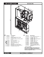
Figure 4-1
4.0 INSTaLLaTION prOceDUreS
4.1 pre-planning the Installation
There is no substitute for planning the installation prior to
beginning the work, minutes in planning may save hours in
installation time. The following items should be taken into
consideration before installing the GeoCenter:
• Allow visual displays on the front of the cabinet to be in
full view of the operator.
• Permit shortest possible tube, wire, and conduit
lengths
• Provide accessibility for adjustments and servicing.
• Provide as much protection from moisture/steam and
heat as possible.
The following items should be taken into consideration before
installing the Sensor. The sensor should be located in an
area of the wash tank that provides:
• A minimum 2" (5 cm) from the tank bottom, sidewall,
overflow piping, etc.
• As far as possible (2" minimum) (5 cm) from heater
elements or coils.
• Protection from physical hazards.
• For constant submersion of all parts of the sensor in
the wash water. This is a particular concern on shallow
tank machines.
NOTE: The S-2000 Sensor is provided with a 12' cable
and mounts from the inside of the washtank. Sufficient
clearance on the inside is required to allow insertion/
removal of the sensor.
NOTE: A S-2000 sensor with 24' cable is available where
necessary (9212-2316).
4.2 Installing the Transformer
1. Mount the plastic transformer enclosure assembly into
the plastic GeoCenter enclosure.
(Refer to Figure 4-1)
.
Attach to plastic GeoCenter enclosure with 8-32 x 5/16
screw in kit bag. Ground using green/yellow wire.
4.3 Mounting the Geocenter
1. Mount the GeoCenter cabinet to the wall using the
supplied screws, washers and plastic wall anchors. The
GeoCenter cabinet may also be installed on top of the
dish machine, using the universal mounting brackets,
and may be the preferred location in some installations.
The installation should be secure, neat and square,
refer to
Figure 4-1.
4.4 Mounting Sensor in Wash Tank
Review Item 4.1, Pre-planning the Installation,
before the
installation begins.
IMPORTANT: Before drilling the hole check for
obstructions both inside and outside of the wash
tank.
1. Cut a 7/8" (22 mm) hole into the wash tank wall.
SCREw
WASHeR
WALL ANCHOR
2.
Properly DEBURR the hole.
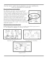
3. Attach the sensor connector to the tank using the pro-
vided metal lock nut and the stainless steel and rubber
washers on both the inside and outside surfaces of
the tank wall. Regardless of which sensor is used, the
packing nut end of the tank connector must be on the
outside of the machine wall,
refer to Figure 4-2.
4. Position the sensor by sliding it through the connector
opening and tightening the packing nut.
4.5 Geosystem Detergent Dispenser
Installation
1. Install the desired Geosystem Detergent Dispenser
following the installation instructions provided for that
unit.
4.6 VaNGUarD Wash Max Installation
1. Install the desired VANGuARD wash Max following the
installation instructions provided for that unit.
S-2000 SENSOR
SENSOR
CABLE
PACKING NUT
PACKING GLAND
Figure 4-2


