background image


12


SAFETY


SYMBOLS


The


machine


is


marked


with


yellow


safety


symbols


with


a


descrip on.


The


meaning


and


placement


of


the


individual


sym

bols


is


explained


below.


The


symbols


should


be


kept


clean


and


legible.


Lost


or


illegible


symbols


should


be


replaced


with


new


ones.


Symbols


can


be


purchased


from


the


manufacturer.


The


legibility


of


symbols


should


be


checked


on


a


regular


basis.


Fig.


1

Obligation to read the 
instructions for use before 
machine operation (on the 
main frame)

Fig. 3


Direction and number of 
frame rotations
(on the front cover)

Fig. 2


Pictogram
(on the main frame

)

12 rpm

The user is obliged to read the instruction manual 

before starting the machine and comply with 

occupational safety recommendations during its 

operation.

Fig.


8

Pictogram
(on the main frame) 

Fig.


9

Direction of rotations
(on the longitudinal cover)

Keep at least 4' away 

from the working machine

12

Fig.


7


Turn off the engine and take out 
the key before starting servicing 
or repairs.
(on the main frame)

Fig.


5

Ban on exceeding the speed 
limit
(on the back cover) 

Fig.


6


Pictogram
(by the roller knife)

Caution -

sharp knives

Fig.


4


Diagram of the film route in the 
dispenser
(on the film dispenser

)

Summary of Contents for EW-450S

Page 1: ...Operator s Manual Parts Breakdown Rev 12 29 14 Model EW 450S Stationary Bale Wrapper ...

Page 2: ...fault of the buyer he she is en tled to submit a complaint to the manufacturer or seller If the user fails to comply with the instruc on manual he she loses his her rights resul ng from the warranty More infor ma on on complaints is contained in the warranty card If nec essary further informa on will be provided by the manufactur er When contac ng the manufacturer or seller please provide the type...

Page 3: ...re than two layers Two months a er the harvest haylage can be fed to animals Using the wrapper for other purposes shall be regarded as im proper use Mee ng and compliance with the condi ons per taining to the use of the machine its opera on repairs accord ing to the manufacturer s requirements form an inseparable part of the requirement for the consistent use with the intend ed use NOTE Exercise p...

Page 4: ...upled with each other by means of a spur gear A roll of wrapping film 17 is installed on the bolt in the dispenser frame in accordance with the diagram see Fig 11 The appropriately selected posi on be tween the rubber rollers and close adhesion of the film 17 to the rollers 16 ensures stretching and good and accurate adhesion to the subsequent film layers The degree of film lengthening can be adju...

Page 5: ... a aching the bale wrapper to the tractor the following ac ons must be taken remove the agricultural hitch from the tractor back the tractor to align it with the bale wrapper both ends of the push pull rods with the ball and socket joints of the tractor should be moved onto two lower bolts and secure them with co er pins adjust the length of the upper connector of the tractor and connect its end w...

Page 6: ... handle from the top and pressed Fig 11 The ends of the film must be pulled through both rolls towards the bale being wrapped A er the film is installed the rubber roll should ad here accurately and evenly to the film roll along the en re length In the case of inaccuracies the film should be adjusted by bending the rod on which the film is installed Fig 11 Film Installa on in the Dispenser 1 Roll ...

Page 7: ...ping Bales should be loaded onto the wrapper using available load ing equipment the li ing capacity of the devices used must be greater than the weight of the bales being wrapped with a possibility of li ing them at a height of 40 Bales should be wrapped at their storage locaƟon to avoid damaging the film during their transport to another loca on Bales should be loaded from the right with the rota...

Page 8: ...ed bale will be unloaded by the white roller to its storage place The wrapping film will be tensioned over the wrapper rollers The wrapper should be lowered to the horizontal posi on and the lower frame should be locked by releasing the line from the driver cab The spring in the lever system should cause the bolt to move automa cally and lock the lower frame Next return to the ini al posi on of th...

Page 9: ... on the flanged holes should be loosened forwards towards the trac tor un l the correct tension is obtained deflec on of approx 20 mm The drive chain 1 can be seen a er unscrewing the trapezoid sheet situated behind the engine in the lower frame The drive chain should be controlled a er wrapping each 100 bales Fig 15 Adjustment of the Drive Chain Tension 1 Main Drive Chain 5 8 2 Nuts M 12 3 Motor ...

Page 10: ...er roll along the whole length place the film dispenser exactly at the height of the axis of the bale bend the bolt on which the film roll is put so that the film adheres evenly to the rubber roll along the whole length 4 The film fed for wrapping bales is not accurately stretched it unfolds when the machine stops A Springs tensioning the arm with rubber rollers are damaged or disas sembled or B T...

Page 11: ...ore star ng any repair adjustment and servicing work at the bale wrapper the engine should be stopped and the igni on key should be taken out of the igni on lock if the wrapper is connected to the hydraulic system 3 During the opera on of the machine near the rota ng frame with a bale being wrapped and while unloading bales at the back of the machine one should make sure that there are no people a...

Page 12: ...rection and number of frame rotations on the front cover Fig 2 Pictogram on the main frame 12 rpm The user is obliged to read the instruction manual before starting the machine and comply with occupational safety recommendations during its operation Fig 8 Pictogram on the main frame Fig 9 Direction of rotations on the longitudinal cover Keep at least 4 away from the working machine 12 Fig 7 Turn o...

Page 13: ...r of Bale Wraps 2 double with overlapping Total Time for Double Wrapping with a diameter of 4 approx 90 seconds Total Number of Wraps for bales with a diameter of 4 30 film 18 wraps 20 film 26 wraps Wrapping Counter Electronic Type of Wrapping Film Special polyethylene film 0 025 0 03mm thick which is stretcha ble self adhesive with ultra violet ray stabilizer Film Wrapping Rotary knives on a fixe...

Page 14: ...g elements should be lubri cated using the ŁT 43 lubricant 1 locking pin of the main frame 1x 2 pins of the main frame suspension 2x 3 pins connec ng the main frame with the lower frame 2x 4 main drive chain 1x 5 drive chains of the rollers 2x 6 bevel wheels of the rota ng frame 1x 7 the track of the bearings on the lower frame 1x 8 edges of roller knives 2x REMEMBER Hydraulic Hoses should be repl...

Page 15: ...15 Table Table Title Page 1 Rotary Table Complete 16 2 Main Frame Complete 18 3 Film Dispenser 21 4 Wrap Counter 23 5 Film Dispenser Set 24 PARTS BREAKDOWN ...

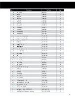
Page 16: ...welded 274 035 400 1 5 Cu er complete 274 037 503 1 6 Bracket welded 274 037 605 1 7 Knife Cover welded 274 037 707 1 8 Bevel Gear Z 17 274 031 011 1 9 Bevel Wheel Z 25 274 031 024 1 10 Frame Gear Cover 274 031 100 1 11 Cover 1 274 031 126 1 12 Cover 2 274 031 113 1 13 Cover 3 op onal 274 031 602 2 14 Knife 274 031 269 2 15 Bolt RE T115 1 16 Handle RE T116 1 17 Nut 274 031 419 1 18 Bearing Se ng 2...

Page 17: ...8 2000 2 36 Washer Z 10 2 FW10 200 14 37 Washer 6 5 FW6 5000 10 38 Washer 10 5 FW10 500 8 39 Chain 10B 76PS PN M 84168 76 2 40 Chain 10B 170PS PN M 84168 170 1 41 Long Sleeve RE T141 1 42 Prisma c Inlet Ax8x7x40 PN M 85005 1 43 Se ng Ring Z25 PN M 85111 8 44 Ball Bearing 6007 2RS B60072RS 2 45 Ball Bearing 6305 2RS B63052RS 8 46 Ball Bearing D 206 PN M 86120 6 47 Short Sleeve RE T147 1 48 Wheel Br...

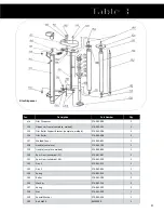
Page 18: ...cking Pin 274 011 262 1 65 Coupling 274 011 288 1 66 Ver cal Beam 274 011 290 2 67 Latch Spring 274 011 310 1 68 Braided Rope 274 011 323 1 69 Clamp 274 011 336 1 70 Block 274 011 351 4 71 Chain 274 011 364 1 72 Barrier welded 274 075 504 1 73 Bracket 411 012 1 74 Bolt M10x25 BM10250 2 75 Bolt M10x70 BM10700 1 76 Bolt M10x35 BM10350 2 77 Bolt M12x25 BM12250 4 78 Bolt M12x35 BM12350 2 ...

Page 19: ...74 021 026 1 95 Semi Circular Cover 274 021 171 2 96 Washer F9x40x4 274 021 232 1 97 Chain Guide 274 021 273 2 98 Plug 6 5 223 890 850 2 99 Bolt M6x25 BM62500 2 100 Bolt M8x25 BM82500 1 101 Bolt M12x90 BM12900 1 102 Bolt M8x25 BM82500 4 103 Bolt 4 8x19 self tapping BMST4819 4 104 Nut M12 NM12000 4 105 Washer 13 FW13000 4 106 Washer Z 6 1 FW6 1000 2 107 Washer Z8 2 FW8 2000 1 108 Washer Z12 2 FW12 ...

Page 20: ... 16 13 150G 2 115 Special Plug 274 051 005 2 116 Connector M22x1 5 overlapping edge 270 121 117 2 117 Washer 270 121 199 6 118 Bolt M12x45 BM12450 2 119 Nut M12 NM12000 2 120 Washer Z12 2 FW12 200 2 121 Body of Elbow Connector PN M 73142 2 122 Lock Nut M16 LNM1600 2 123 Gasket 13 3x2 4 PN M 86961 2 ...

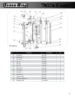
Page 21: ... 2 127 Welded Cover 274 045 601 1 128 Handle complete 274 045 703 1 129 Handle complete welded 274 045 805 1 130 Spur Gear cylindrical 21 274 041 007 1 131 Spur Gear cylindrical 34 274 041 010 1 132 Disc 1 274 041 022 1 133 Disc 2 274 041 035 1 134 Spring 274 041 050 1 135 Roller 274 041 109 2 136 Washer 274 041 226 2 137 Spring 274 041 302 2 138 Nut 274 041 330 1 139 Special Washer 274 041 356 1 ...

Page 22: ...x35 BM12350 2 144 Nut M6 NM60000 2 145 Nut M12 NM12000 4 146 Nut M12 NM12000 2 147 Washer M13 FW13000 10 148 Washer M13 FW13000 2 149 Washer Z6 1 FW6 1000 2 150 Washer Z12 2 FW12 200 4 151 Spring Pin 6x28 RE T3151 1 152 Ball Bearing 62032RS B62032RS 4 153 Se ng Ring Z38 PN M 82005 1 Film Dispenser ...

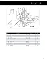
Page 23: ...ounter 274 106 200 1 154 Rota on Sensor 274 106 108 1 155 Remote 274 106 200 1 156 Washer M13x28x2 223 890 554 2 157 Bracket 223 890 977 3 158 Bolt M6x25 BM62500 3 159 Nut M6 NM60000 3 160 Washer Z6 1 FW6 1000 3 161 Nut M12 NM12000 2 Wrap Counter ...

Page 24: ...r Film Bracket RE T503 1 4 Lock RE T504 1 5 Spring 1 RE T505 1 6 Lid RE T506 1 7 Spacing Sleeve RE T507 1 8 Spur Gear Z11 RE T508 1 9 Tensioner Roller set RE T509 2 10 Se ng P205 RE T510 8 11 Spacing Sleeve 3 RE T511 2 12 Spur Gear Z12 RE T512 1 13 Film Compression Sec on RE T513 2 Film Dispenser Set ...

Page 25: ...0 2 25 Nut M6 NM60000 2 26 Nut M6 NM60000 2 27 Washer 8 4 FW8 4000 3 28 Washer 10 5 FW10 500 2 29 Washer 6 5 FW6 5000 2 30 Bearing 608Z B608Z 1 31 Ring W 22 RE T531 1 32 Bearing FD205 BFD205 4 33 Roller Chain 08B 1 2 RE T533 1 34 Connec ng Link 08B RE T534 1 35 Lock Nut M27 LMN2700 1 36 Ring Z 30 RE T536 2 37 Bolt M12x70 BM12700 1 38 Nut M12 NM12000 1 39 Washer 13 FW13000 2 40 Dowel 6x45 D64500 1 ...

Page 26: ...26 ...

Page 27: ...defective in material or work manship This limited warranty does not apply to and excludes wear items such as chains knives blades or other wear items Oil or grease is not covered by this warranty All obligations of Belco Resources Equipment under this limited warranty shall be terminat ed if Proper service is not preformed on the machine The machine is modified or altered in any way The machine i...

Reviews: