background image


- 11 - 


Also an all-pole air-break switch is needed and the pole clearance should be more than 3mm.


The ground wire must be well connected. Ground wire can’t be connected to coal gas pipe, water 

pipe or telephone wire. 


The supply power must have over voltage and low voltage protection equipment. Make sure no 

phase disorder (L1 to R, L2 to S, L3 to T). Suppose phase disordered, system can’t be started, and no 

display in controller. 


Drain electricity protection switch is needed for the system. No drain electricity protection switch 

may cause electrical shock. 


The operation handle of power switch is suggested to be black or gray, and it can be fixed at OFF 

status.  The  installation  location  of  power  switch  is  suggested  among  0.6  to  1.7  m.  electrical  short 

circuit protection is needed.   


If  the  supply  cord  is  damaged,  it  must  be  replaced  by  the  manufacturer  or  its  service  agent  or  a 

similarly qualified person in order to avoid a hazard. 


dispose 


Do not dispose this product as unsorted municipal waste. Collection of such waste separately for 

special treatment is necessary.   


Meaning of crossed-out wheeled dustbin: Do not dispose of 

electrical appliances as unsorted municipal waste, use separate 

collection facilities. 


Contact you local government for information regarding the 

collection systems available. 


If electrical appliances are disposed of in landfills or dumps, 

hazardous substances can leak into the groundwater and get into the 

food chain, damaging your health and well-being. 


When replacing old appliances with new ones ,the retailer is legally obligated to take back your old 

appliance for disposal at least free of charge. 


It is prohibited to dispose of this appliance in domestic household waste. for disposal there are 

several possibilities: 

a)


The municipality has established collection systems, where electronic waste can be disposed of at 


Summary of Contents for CAM-20XB

Page 1: ...www econo nl Manual heatpump model Econo CAM ...

Page 2: ...king principle 7 2 3 Figure dimension 8 3 Installation Instruction 8 3 1 Installation 8 3 2 Water system installation chart 12 3 3 Electrical diagram 14 3 4 System test 15 4 Panel operation 17 4 1 Mode and temperature display area 17 4 2 Time and timing display area 17 4 3 Button describe 18 4 4 Operation function 18 5 Malfunction protection and code 22 ...

Page 3: ...at water reducing running costs Full Functional Full Functional Full Functional Full Functional Compared with other products Air condition and water heater integrated unit has a comprehensive function can be provided air condition cold water or sanitation heat water by oneself as well as Air condition and water heater integrated of three kind functions In Winter it can be provided air condition he...

Page 4: ... safe operation The microelectronics controller can start or switch off the machine by judging the water temperature If the water temperature is lower than designed water temperature the machine will be switch off to avoid freezing The microelectronics controller can also supervise the status of components Malfunction occurred would be transmitted to the controller and displayed through malfunctio...

Page 5: ...eated water condition COP kW kW 4 7 kW 12 4 Rated cooling capacity kcal h 10659 9 Rated water flow air condition T h 2 1 Cooling power Input kW 4 3 Cooling running Current A 7 6 Cooled water condition air c ondition E E R kW kW 2 9 kW 13 2 Rated heating capacity air condition kcal h 11346 1 Rated water flow T h 2 3 Heating power Input kW 4 0 Heating running current A 7 6 Heated water condition air...

Page 6: ...ter condition Rated environment temp 18 23Deg C heating water temp 15 55Deg C Cooled water condition air condition Rated environment temp 32 36Deg C cooling water temp 12 7Deg C Heated water condition air condition Rated environment temp 7Deg C cooling water temp 40 45Deg C The same to water flow in the summer Alliance for cool and heat conditions Heating water temp 15 55Deg C cooling water temp 1...

Page 7: ... er I nl et cool i ng w at er He a t i n g f l o w 1 Compressor 2 Four way valve 3 heat exchanger 4 Pressure switch 5 Pump 6 Drier and Filter 7 Liquid tank 8 Thermal Expansion Valves 9 Fan 10 Fin tube heat exchanger 11 Gas liquid segregator 12 Low pressure switch 13 High pressure switch 14 Tube in tube heat exchanger ...

Page 8: ... be done by qualified professionals Make sure the installation match installation match installation match installation matching ing ing ing the following conditions the following conditions the following conditions the following conditions The selection of installation location The installation location must match the following conditions Make sure the installation environment is open surrounding...

Page 9: ...ion of condensing air flowing Make sure that the released air from condenser or unit operating noise will not impact the living of neighbor The unit must be installed firmly and the bottom of unit must be horizontal the gradient must be less 5 degree Keep enough space between the machine and wall It is convenient for unit s repairment and maintenance and also you shouldn t lay the pipelines and to...

Page 10: ...Shutoff valve and so on Heating pipe must be equipped with Soft tie in a water filter One way valve Flow meter Drain valve Shutoff valve And then connected to underground inlet outlet water pipe Drain cock should be installed at the highest point of hydraulic circle After the hydraulic circle is connected completely exhaust air inside hydraulic circle Drain valve should be installed at the lowest ...

Page 11: ...placed by the manufacturer or its service agent or a similarly qualified person in order to avoid a hazard dispose Do not dispose this product as unsorted municipal waste Collection of such waste separately for special treatment is necessary Meaning of crossed out wheeled dustbin Do not dispose of electrical appliances as unsorted municipal waste use separate collection facilities Contact you loca...

Page 12: ...ood chain Warning 3 2 3 2 3 2 3 2 Water Water Water Water system system system system installation chart installation chart installation chart installation chart 10 Indoor terminal 12 12 4 5 5 Storage water tank Expansion Tank 15 13 14 O utl et heated w ater Inl et w ater 14 14 15 15 Warning Any abnormal accident such as burning smell switch off the machine immediately Contact Warning It is forbid...

Page 13: ...can be finished according to above chart NOTES A Please do exhaust the air in water system before running the machine if you completely finished the circulating water system piping B The water flow switch must be installed at the straight pipeline section of the same level from the elbow valves and other pieces of partial resistance to more than 5 times the diameter C The pipe must be insulated cl...

Page 14: ... condi t i on TH 1 Sensor of ent eri ng w at er t em p ai r condi t i on TH 3 Sensor of am bi ent t em p D ot t ed l i ne i s used f or t he cl i ent connect i on part M odel C AM 20XB TH 4 Sensor of def r ost t em p 1 TH 5 Sensor of def r ost t em p 2 TH 7 Sensor of di schar ge t em p 1 TH 8 Sensor of di schar ge t em p 2 heat er w at er ai r condi t i on El ect r om agnet i c val ve El ect r om ...

Page 15: ...ecking to make sure required voltage and current are available 3 Pressure inside hydraulic circle reaches to operating pressure 1 3 kgf cm2 4 Make sure hydraulic system inside is clean and no jam 5 make sure hydraulic circle is fully filled with water and no air inside 6 Check to make sure all valves are switched on well thermal isolated 7 Make sure all electrical wires are connected correctly acc...

Page 16: ... conduct a comprehensive inspection to confirm compliance with requirements may be an overall commissioning pre commissioning the compressor should be warm up 12 hours a day 1 connected to power to open several air conditioners host delay to start after three minutes Fans water pumps steering is correct if not immediately turn off the power whether the current measurement of the normal operation o...

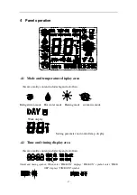
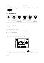
Page 17: ...s Refrigeration mode Hot water mode Heating mode automatic mode Week display Setting parameter and control temp display 4 2 Time and timing display area this area reality content includes legend as follows On off and timing symbol When enter TIME ON displays TIME ON symbol enter TIME OFF displays TIME OFF symbol ...

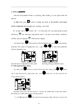
Page 18: ... The communication distance of up to 30 meters 2 Power source DC 12V 10 3 Display content describe in normal working Display various parameters of state of water cooled chiller Example 1 Start the unit refrigeration mode backwater temp 25 time currently Monday 8 30a m The state of output currently compressor output on off timing running shows on If the unit has malfunction in running automatically...

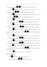
Page 19: ...ress button enter set the parameter scan press button again and enter the sensor of temperature scan press to select the parameter which is needed to scan Scan the sensor temperature sensor status browsing settings parameter status 5 System parameter setting In normal press button 3 seconds enter the parameter setting press button may be adjusted upwards or downwards then press button last 3 secon...

Page 20: ...ds or downwards 6 Press button once and enter the parameter setting of the sixth section set the ambient temp for running electric heating then press button may be adjusted upwards or downwards 7 Press button once and enter the parameter setting of the seventh section set the waiting time for defrosting then press button may be adjusted upwards or downwards 8 Press button once and enter the parame...

Page 21: ...ek timer has 7 groups Through press button last 3 seconds to switch 7 groups timing the week display section shows all the marking of Monday to Sunday 8 Parameter setting User settings refers to the user according to the local climate and environment set the unit s operating parameters the table is bellowing Parameter settings all parameters must be set up in off mode to be effective ...

Page 22: ...lock E 1 XX malfunction malfunction code Parameter setting Max Min Regulation accuracy Factory settings Refrigerating temp setting 25 3 1 12 Heating temp setting 50 25 1 40 Tank temp setting 20 70 1 55 antifreeze temp in winter 12 5 1 3 leaving water temp setting cooling 12 5 1 3 set the ambient temp for running 12 5 1 3 Defrost waiting time 90min 20min 1min 45min Defrost running time 25min 5min 1...

Page 23: ... 23 ...

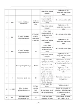
Page 24: ... malfunction air condition E2 Temperature probe is damaged Replacement of the corresponding temperature probe Circuit board temperature probe is not inserted well or loose Re insert temperature probe 3 TH3 Sensor of ambient temp malfunction E3 Temperature probe is damaged Replacement of the corresponding temperature probe Circuit board temperature probe is not inserted well or loose Re insert temp...

Page 25: ...ure probe is damaged Replacement of the corresponding temperature probe Expansion valve opening is too small Adjust thermal expansion valve opening larger System has a leak Refrigerant leak detection and re filling 9 Discharge temp 1 too high EB EC Temperature probe is damaged Resistance produce changes Replacement of the corresponding temperature probe 9 Antifreeze protection ED In winter the amb...

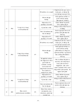
Page 26: ...have a period of time scaling phenomenon washing unit operation will have a period of time scaling phenomenon cleaning 15 IN3 Comp 2 high voltage switch malfunction F3 Temperature reflects the temperature of the probe failed to establish Causing water tank water temperature lower than the actual water temperature actually Check whether the probe is inserted a true reflection of water tanks and wat...

Page 27: ...hange the water pump to increase flow Water flow switch is not properly access electronic control box terminal row join Regulation of water flow switch spring preload adjustment is incorrect resulting in insufficient water flow but flow switch does not close To re install the flow switch Water flow switch is not installed correctly the wrong direction flow switches valve selection error To re inst...

Reviews: