background image


PoolMaster

pro

™ 

Solar Pool Heating System   --  Installation & User Manual  

© Copyright 2020  Optex Solar Pty Ltd. All rights strictly reserved. 


Page 27


16


Roof Assembly and Attachment 


16.1


Tile Roof Mounting of Manifold Assembly 


When working with power or hand tools always follow the safety instructions. Wear the 
recommended personal protective apparel. Make sure electrical cables are kept away from 
any water and from foreign objects which pose 

a potential cable severing or crushing hazard

When using glues, solvents or sealing agents make sure 

you know and seek the proper first 

aid

 in case of an accident. 

Summary of Contents for PoolMasterpro

Page 1: ...r otherwise without the specific written permission of Optex Solar Pty Ltd Trademarks appearing in this manual are the sole property of Optex Solar Pty Ltd or their respective owners Nothing in this publication shall be construed as granting any express or implied license to use any intellectual property of Optex Solar Pty Ltd otherwise than for personal and non commercial use only Optex Solar Pty...

Page 2: ...r Array 13 Collector Water Flow Configurations 13 1 Bottom Feed Basic Square Parallelogram or Trapezoid 13 2 Top Feed Basic Square Parallelogram or Trapezoid 13 3 Narrow Roof Space Multi Loop Configuration 13 4 Narrow Roof Space Extra Manifolds Configuration 13 5 Other Custom Narrow Roof Space Extra Manifolds Configurations 13 6 Double Manifold High Flow Narrow Roof Space Configuration 13 7 Bottom...

Page 3: ...endent Separate System 19 2 Configuration 2 Integrated Independent System 19 3 Notes on Teeing into the Suction Line for Configuration 2 19 4 Configuration 3 Manual Timer Motorized Valve System 19 5 Configuration 4 Booster Retrofit System 20 Installing the Controller for Independent Systems 20 1 Installing the Roof Hot Sensor 20 2 Installing the Pool Cold Sensor 20 3 Extending Sensor Cords 21 Drai...

Page 4: ...ducts without reading safety guidelines in the manual Please report any product safety issues or near misses to info EcoOnline com au no matter how trivial Refers to useful information for the optimal operation of the system Indicates a SAFETY issue that is likely to cause injury or death if the user does not follow the instructions Indicates a SAFETY issue that may cause injury or death if the us...

Page 5: ...aller invests in roof safety guard rails and a safety harness system especially for DIY applications Building regulations vary from state to state and MUST override any instructions supplied in this manual It is the responsibility of the purchaser installer to check that installations comply with any relevant state laws and regulations Collectors are to be used with chlorinated or otherwise saniti...

Page 6: ... much larger pool temperature boost when used in conjunction with a solar pool heater due to synergistic effects So much so that if you re running a solar pool heater and not using a pool cover you are missing out on surprisingly large temperature gains see link below for the summaries www EcoOnline com au how warm can a pool get with a solar heater and cover So if you ve used a pool cover before ...

Page 7: ...ably see Installing a By Pass Tube or By Pass Ball Valve below Lastly you may need to run your main filter pump in the afternoon to help mix the warm water if your pool volume turnover falls below the 50 75 range 6 2 Quick Reference Solar Pump Sizing for Independent Systems The two tables below will give you the minimum and maximum Australian Standard pump power recommendations for independent typ...

Page 8: ... m2 200 L min 660 Watts 0 88 HP 770 Watts 1 03 HP 43 m2 217 L min 700 Watts 0 94 HP 820 Watts 1 10 HP 47 m2 233 L min 750 Watts 1 00 HP 870 Watts 1 17 HP 50 m2 250 L min 800 Watts 1 08 HP 930 Watts 1 24 HP 53 m2 267 L min 860 Watts 1 15HP 980 Watts 1 32 HP 6 2 1 Example Pump Sizing For example for a large 75 000 Litre pool and 1st story roof your minimum Australian Standard pump specs from the fir...

Page 9: ...ing Sizing for Solar Pool Heating System Lines Anticipated Flow Rate Absolute Minimum Ideal PVC Pipe Size Maximum Pipe Size 70 Litres min 20 PVC DN20 25 PVC DN25 32 PVC DN30 120 Litres min 25 PVC DN25 32 PVC DN30 40 PVC DN40 200 Litres min 32 PVC DN30 40 PVC DN40 50 PVC DN50 250 Litres min 40 PVC DN40 50 PVC DN50 65 PVC DN65 400 Litres min 50 PVC DN50 65 PVC DN65 80 PVC DN80 880 Litres min 80 PVC ...

Page 10: ...ing collars 1 silicon tube per 4m2 kit 1 Pipe clamp 0 5m band for fixing per 4m2 kit Other Essential System Components depending on system purchased 1 32 40 PVC Vacuum breaker valve 1 Can of silicon lubricant spray 1 Drain Down Kit 2 28 locking collar for repair kit 1 14 joining barb repair kit 1 In line pressure gauge For Manual Systems depending on purchase For Independent Systems depending on p...

Page 11: ...crewdriver Safety glasses Corking gun for Silicon glue Hack saw Gloves Personal Sun UV protection Assorted drill bits Power Lead Heat Gun Tape measure Tin snips Industrial Ladder Needle nose pliers Power Lead Scissors Old cloth for silicon over spray Hammer Appropriate PVC piping Various PVC plumbing bits N P type PVC cement primer Fixing screws for perforated band Cable ties for fixing thermostat...

Page 12: ...ced on solid ground and should ALWAYS be securely anchored at the base and secured at the top to prevent slipping 12 Choosing a Place to Install the Collector Array When choosing a location for your collector array you should consider the following in order of importance Shading the collector array should receive no shading between the hours 10am to 4pm Direction collectors should preferably face ...

Page 13: ...llelogram or Trapezoid The collector array can face anywhere from West to East with an optimal orientation of North for most areas South facing orientations are generally not recommended unless the roof pitch is quite flat 5 for southern states and 15 for northern states All collector array configurations must be installed with a vacuum release valve on the return line and a non return valve on th...

Page 14: ...hieve balanced water flow in each strip Either up the roof for bottom feed system or down the roof for top feed systems Why Without the third balance pipe water always takes the shortest path reducing flow in the higher tube strips Top feed configurations should operate at lower pressure of 50 kPa max and are not recommended for areas subject to freezing conditions overnight Why It is impossible f...

Page 15: ...r Pool Heating System Installation User Manual Copyright 2020 Optex Solar Pty Ltd All rights strictly reserved Page 15 13 3 Narrow Roof Space Multi Loop Configuration 13 4 Narrow Roof Space Extra Manifolds Configuration ...

Page 16: ...required 1400 mm 13 6 Double Manifold High Flow Narrow Roof Space Configuration Straight strips runs manifolds on both sides Array Length Manifold Count per role Array Width per role 12 5 m 4 2 extra required 350 mm 8 33 m 6 4 extra required 525 mm 6 25 m 8 6 extra required 700 mm 5 0 m 10 8 extra required 875 mm 4 167 m 12 10 extra required 1050 mm The extra manifold configuration is recommended ...

Page 17: ...ting System Installation User Manual Copyright 2020 Optex Solar Pty Ltd All rights strictly reserved Page 17 13 7 Bottom Feed Overlap Square Parallelogram or Trapezoid 13 8 Top Feed Overlap Square Parallelogram or Trapezoid Layout ...

Page 18: ...om Feed Butterfly for long 25m collector arrays Top feed configurations should operate at lower pressure of 50 kPa max and are not recommended for areas subject to freezing conditions overnight Why It is impossible for the water to drain full from a top feed system Freezing conditions with excess water inside piping can lead to PVC pipes cracking ...

Page 19: ...PoolMasterpro Solar Pool Heating System Installation User Manual Copyright 2020 Optex Solar Pty Ltd All rights strictly reserved Page 19 13 10 Top Feed Butterfly for long 25m collector arrays ...

Page 20: ...ompass directions are not recommended unless the roof pitch is less than 15 In this case the temperature sensor should be installed at an angle that is an average of the two collector array directions Installations with a purely south facing facet are still not recommended for southern areas of Australia Why Depending on the location of the roof sensor the controller could turn the system on with ...

Page 21: ...cing different compass directions should only be installed on flat roofs with pitch no more than 30 In this case the temperature sensor should be installed facing an angle that is an average of the two collector facet compass directions preferably weighted toward the compass direction of the larger area facet Why Depending on the location of the roof sensor the controller could turn the system on ...

Page 22: ...ed In Parallel Split Arrays For Multi Level Split Arrays An in parallel configuration is recommended for installing two different arrays on any differing or similar levels For split flow multi level arrays at substantially different heights 1m a ball valve constriction MUST be installed to limit flow to the collector array installed at the lower level ...

Page 23: ...lumbing Configurations Not Recommend An in series configuration can be installed when you need to split an array However note for this configuration the bottom array will receive much greater pressure Depending on the height of the top array and the pump size this could over pressurize the bottom array We recommend this array is used only if the height difference between the two arrays is no more ...

Page 24: ...PoolMasterpro Solar Pool Heating System Installation User Manual Copyright 2020 Optex Solar Pty Ltd All rights strictly reserved Page 24 ...

Page 25: ...etween Strips 500mm uncut 60mm 480mm 2nd notch 50mm 460mm 4th notch 40mm 440mm 6th notch 30mm 420mm 8th notch 20mm 400mm 10th notch 10mm minimum gap 15 Adjusting Strip Spacing for Angled Manifold Runs For installations where the manifold assembly needs to run at an angle to the slope of the roof the spacing between collector strips will depend on the manifold angle and manifold length The template...

Page 26: ...PoolMasterpro Solar Pool Heating System Installation User Manual Copyright 2020 Optex Solar Pty Ltd All rights strictly reserved Page 26 ...

Page 27: ...Manifold Assembly When working with power or hand tools always follow the safety instructions Wear the recommended personal protective apparel Make sure electrical cables are kept away from any water and from foreign objects which pose a potential cable severing or crushing hazard When using glues solvents or sealing agents make sure you know and seek the proper first aid in case of an accident ...

Page 28: ...PoolMasterpro Solar Pool Heating System Installation User Manual Copyright 2020 Optex Solar Pty Ltd All rights strictly reserved Page 28 16 2 Corrugated Metal Roof Mounting of Manifold Assembly ...

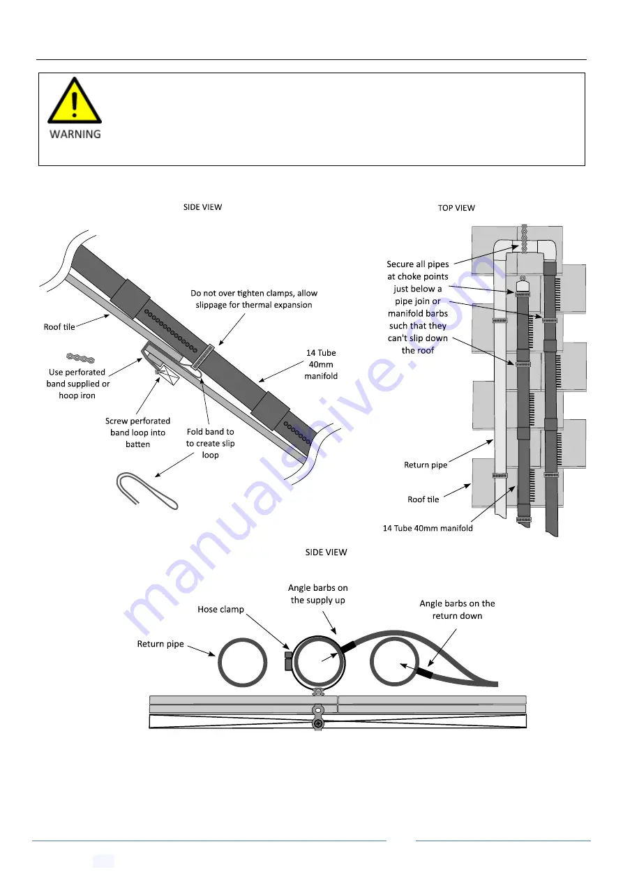
Page 29: ...art Work quickly inert male part into female socket immediately after cement application Twist one way then the other to spread any glue align tool marks and hold in place for a moment Wipe any excess to prevent cement induced stress cracking Take care not to overspray silicon on a critical part of the roof as this will create poor silicon glue adhesion and a dangerous slippery working environment...

Page 30: ...the webbing first Use needle nose pliers to pull out webbing Consider the passage of water under the collector Make sure water can still drain and run under the collector On very flat tile you will need to lay a vertical strip of spare collector tube at periodic lengths to allow drainage under the collector strip When gluing the strip start from the manifold Glue the first part then place a couple...

Page 31: ... rights strictly reserved Page 31 17 Extra Wind Proofing Coastal region boundaries are smooth lines set in from a smoothed coastline by 50km 100km or 150km lines If you are in Wind Regions B C or D or situated on a hill or in open terrain you will need to increase the above specified frequency of fixings ...

Page 32: ... Ltd All rights strictly reserved Page 32 17 1 Roof Edge Exclusions Zones Note Strips installed near or within a roof edge exclusion zone require 2 X the fixing strength in that local area Strips installations within a roof corner exclusion zone require 3 X the fixing strength in that local area ...

Page 33: ...and attachments and fix loosely at first using hose clamps 7 Lay the collector strips out 8 Cut the collector strips near the base of the respective barb manifold and connect the tubes to the barbs 9 Glue remaining pipe work and vacuum release valve in place 10 Tighten the hose clamps to secure the manifolds while still allowing for some thermal expansion 11 Drill 8 5mm hole and install pressure g...

Page 34: ...tages More energy efficient as a small solar pump runs independent of the large main filter pump Requires separate solar suction provisions to be installed When constructing pipe work consider the thermal expansion of long lengths of pipe work and the stress this produces on joins Note the minimum spacing for PVC 40 pipe supports is 900m less for smaller pipes Use the perforated band to create sad...

Page 35: ...ages More energy efficient as a small solar pump runs independent of the large main filter pump Can be retrofitted to older pools depending on access to underground suction line Pumps can t run simultaneously for pools with only 1 return port Suction tees above or only just below the water line will require regular maintenance of non return valves Filter pump must be set on a timer to run outside ...

Page 36: ...equire it A standard flap non return will not suffice Also note such a system will need regular careful maintenance of the solar and filter line non returns Any failures or even the smallest leaks in these non returns due to twigs or grit getting into the rubber seal will pass air and eventually de prime pumps Filter pump must be set on a timer to run outside of solar hours to exclude the possibil...

Page 37: ...ors Large main filter pump needs to run all day for solar Can be retrofitted to pools that don t have separate solar provisions Motorized three way valve and controller can be retrofitted later Requires specialized motorized valve and controller to automate Increases pressure and decreases flow rate in the filter system Not recommended for two story installations For manual pool heating systems ru...

Page 38: ...antages Disadvantages Less extra plumbing is required for solar Requires second pump and special controller Only filtered water runs through collectors Does not require separate solar suction provisions Large main filter pump solar pump need to run all day for solar This configuration is not recommended for single story installs for pools with only a single return port due to the potential over pr...

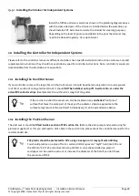
Page 39: ... roof sensor it should be adhered using silicon to a sun exposed roof tile or section of corrugated metal roof It should NOT be installed on top off inserted into or under the actual PVC collector strips Ideal placement is within arm s length of the gutter 20 2 Installing the Pool Cold Sensor The cold sensor should be fitted inside a section of PVC suction line before the solar pump and sealed usi...

Page 40: ...r booster pump and flushing the pump with clean water for storage over winter The use of a water tight non return valve on the solar supply will prevent drain down which could result in water freezing inside PVC piping in frost prone areas and or hot water stagnation in summer Any non return valves installed on the supply line MUST have a 6mm drain hole drilled in the flap to allow drain down Why ...

Page 41: ...r grommet into the hole first and then insert the single barb side barb into the grommet Finally connect the by pass tube to the double barb side barb ends 22 Optimizing Collector Pressure 22 1 Installing the Pressure Gauge The pressure gauge must be installed on the return line preferably near eye level Drill into the PVC pipe using an 8 5mm drill Insert the rubber grommet into the hole tapered e...

Page 42: ...it may be that your pump cannot positive pressurize the vacuum release valve In this case you will get undesirable constant bubbling in the outlet to the pool as the vacuum release valve is at negative pressure and is drawing in air If this happens you will need to install the down draft brake PVC ball valve 16 on the return line see plumbing diagrams and carry out the following procedure Start th...

Page 43: ...g procedure carried out only once during installation to limit pressures inside the panels 1 Removed any potential constrictions in the return line going back into the pool such as eyeballs in the return outlets 2 If pressure is still too great as measured at the pressure gauge see above Pressure Check Procedure install a by pass ball valve 19 see plumbing diagrams 3 Turn the solar pump on with th...

Page 44: ...ded X Debris Accumulation Check that there is no build up of debris around pipe work or collectors and that water has a clear path to run down X Winterizing System You may need to prepare your system for winter dormancy each year X 24 1 Collector Puncture Repair Procedure Locate the leak cut a 3mm cross section of tubing strip webbing and thread the locking sleaves Lubricate barb joiner using sili...

Page 45: ...ter flow A non return valve was installed with a small 6mm hole drilled in the flap The drain equalization tube was installed on the supply and return line Collectors should run and be adhered to the top of ridges of any roof structure not the valleys to allow water and debris drainage Frost proofing was considered All PVC lines are sloped such that water runs back into the pool at night Solar con...

Reviews: