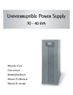
background image


Summary of Contents for 30 kVA

Page 1: ......

Page 2: ...ormance This manual contains detailed instructions on how to use and install this product For information on how to use this equipment and obtain the best performance this manual must be carefully kep...

Page 3: ...ECK OF CONTENTS 64 POSITIONING THE UPS 64 OPERATIONS TO ACCESS THE TERMINALS OF THE UPS 64 ELECTRICAL CONNECTIONS 65 DIAGRAMS OF CONNECTIONS TO THE ELECTRICAL SYSTEM 65 UPS INTERNAL PROTECTIONS 68 EXT...

Page 4: ...WER SUPPLY FOR AUTOMATIC BYPASS 82 AUXILIARY POWER SHARE AND POWER OUT SOCKETS OPTIONALS 82 POWER WALK IN 82 POWER REDUCTION FOR 200 208V PHASE NEUTRAL LOADS 82 CONFIGURING THE UPS 83 COMMUNICATION PO...

Page 5: ...CT SOURCE ensures low input distortion a power factor close to 1 and maximum generator set compatibility BATTERY CARE SYSTEM allows a customised management for different battery types and their contin...

Page 6: ...55 FRONT VIEWS OF THE UPS Control panel with graphic display Wheels for moving the UPS Front door with lock Brake rod Ventilation grid...

Page 7: ...ate bypass isolator optional Manual bypass isolator Output isolator From the left Battery start button COLD START R E P O Remote Emergency Power Off connector Contact holder for AS400 USB communicatio...

Page 8: ...IONS Power connections EXTERNAL BATTERY INPUT SEPARATE BYPASS optional OUTPUT Connection for external synchronization signal Connection for remote maintenance bypass command Connection for external Ba...

Page 9: ...58 REAR VIEW OF THE UPS Parallel board slot optional Power board fans Powershare socket Power out socket Battery charger fan Power relay board slot optional...

Page 10: ...wer LED Low battery LED Battery power LED ECO mode LED Load on bypass LED Graphic display Stand by alarm LED F1 F2 F3 F4 FUNCTION KEYS The function of each key is indicated at the bottom of the displa...

Page 11: ...LINES The UPS series with Separate Bypass allows a separate connection between the input and the bypass lines The UPS output is synchronised with the bypass line in order to avoid incorrect voltage ch...

Page 12: ...tery 1 1 4 kW 1205 kcal h 4780 B T U h 1 5 kW 1290 kcal h 5120 B T U h Dissipated power with nominal distorting load pf 0 7 and charged battery 1 1 34 kW 1150 kcal h 4565 B T U h 1 35 kW 1160 kcal h 4...

Page 13: ...bient temperature remains between 0 and 40 C while the UPS is operating This UPS can operate with an ambient temperature between 0 and 40 C The recommended working temperature for the UPS and the batt...

Page 14: ...USP door Remove the 2 brackets securing the UPS to the pallet by unscrewing the screws marked A and B in the figure The previously removed brackets can also be used as slides Secure the slides to the...

Page 15: ...the wall to allow the air blown by the ventilation fans to outflow correctly No objects should be placed on its upper surface Once the equipment has been positioned secure it with the apposite brake...

Page 16: ...utral PE protective earth of TT TN or IT type Therefore the phase rotation must be respected Optional TRANSFORMER BOXES to convert the distribution systems from 3 wires to 4 wires are available DIAGRA...

Page 17: ...UPS with no modification of the neutral regime and with separate bypass input UPS with input galvanic isolation and with separate bypass input UPS with output galvanic isolation and separate bypass in...

Page 18: ...efer to the same potential In case the two power supplies were different an isolation transformer would be necessary on one of the inputs UPS with no modification of the neutral regime and with separa...

Page 19: ...ese values also depend on the UPS operating status at the time of the fault which can be either UPS in NORMAL OPERATION the load is instantly commutated to the bypass line UPS 30kVA I2 t 20000A2 s UPS...

Page 20: ...tput This way the neutral regime of the equipment is not modified THE INPUT NEUTRAL IS CONNECTED TO THE OUTPUT NEUTRAL THE DISTRIBUTION SYSTEM THAT POWERS THE UPS IS NOT MODIFIED BY THE UPS WARNING ma...

Page 21: ...can be inserted in the terminal board is 25 mm2 for trailing cables 35 mm2 per rigid cables CONNECTIONS As for UPSs with separate bypass please see the subsequent paragraph The very first connection...

Page 22: ...be installed remove the short circuit and connect to the normally closed contact of the stopping device by using a cable that ensures a double isolation connection In case of emergency the R E P O co...

Page 23: ...he UPS Use cables with cross sections in compliance with the indications given in the Cross section of the cables paragraph In order to connect the SERVICE BYPASS terminal to the auxiliary contact of...

Page 24: ...make sure that SWBATT fuse holders of the UPS and Battery Box are open Before making any connection read carefully the instructions in the Battery Box manual Connect the cables coming from the Battery...

Page 25: ...re inside a remote Battery Box It is essential that only the kit provided by the manufacturer is used Any uses not conforming to the specifications may cause faults or breakdowns of the equipment As f...

Page 26: ...ttery efficiency The UPS block diagram is shown below with a description of its individual components UPS block diagram IMPORTANT Our UPSs are designed and built for long durability even under the mos...

Page 27: ...ith the instructions given in Connecting the UPS to the Battery Box optional paragraph the battery fuses and other protections may result damaged In that case please contact the Customer Service depar...

Page 28: ...ications on the terminal board Close the protective panel again Repeat the preliminary operations given in the previous page Press the button to access the start up menu Press YES when requested to co...

Page 29: ...lay will turn on Press the button to access the start up menu When requested to confirm press YES and then press the button again to confirm All LEDs on display will turn on for about a second and the...

Page 30: ...re pages containing all the data referred to the menu chosen UPS STATUS ERRORS FAULTS This area of the display shows the UPS operating status The first line is always active and constantly shows the c...

Page 31: ...80 MENU DISPLAY...

Page 32: ...ualified personnel may cause harm to the operator and damage to the equipment Listed below are the operations to be performed in order to carry out the maintenance on the equipment with no interruptio...

Page 33: ...e Power out socket is connected directly to the UPS output and it is useful to power accessories such as modems for example Safety notes when the UPS is switched on if the output isolator SWOUT is ope...

Page 34: ...Sets the maximum time of battery operation Disabled Disabled complete battery discharge 1 65000 in steps of 1 sec SW Low battery pre alarm Sets the estimated autonomy time left for low battery warning...

Page 35: ...abled High sensitivity Enabled Low sensitivity Disabled with input output synchronisation Disabled without input output synchronisation SW Inverter synchronization External Sync Selects the synchronis...

Page 36: ...2 CONNECTOR USB CONNECTOR PIN NAME TYPE SIGNAL PIN SIGNAL 1 IN 1 VBUS 2 TX OUT TX serial line 2 D 3 RX IN RX serial line 3 D 4 4 GND 5 GND POWER 6 OUT 7 8 15V POWER Isolated power supply 15V 5 80mA ma...

Page 37: ...mains voltage the UPS resumes operating from the inverter If the jumper is removed in absence of the mains voltage the UPS resumes operating from the battery 4 5 12 BATTERY LOW OUTPUT 1 Indicates tha...

Page 38: ...B This signal is made when the UPS commutates to bypass in order to compensate the surge current due to the insertion of a distorting load Sound C This signal is emitted when the UPS switches to batte...

Page 39: ...ions given by the installation program For further information on how to install and use the software please consult the manual provided in the Manuals folder of the CD Rom provided To check for a mor...

Page 40: ...sence of this connection could damage the UPS and the load Connect the mains to the terminals following the indications in the paragraph on Installation THE ISOLATOR BEHIND THE DOOR SWIN IS OPEN Close...

Page 41: ...S off and back on again and exclude the maintenance bypass If the problem persists contact the nearest service centre PHASE 1 HAS A MUCH LOWER VOLTAGE THAN THE OTHER TWO PHASES Open the SWIN switch on...

Page 42: ...TERIES ARE DISCHARGED THE UPS WAITS FOR THE BATTERY VOLTAGE TO EXCEED THE SET THRESHOLD Wait for the batteries to recharge or force startup from the SYSTEM ON menu THE DISPLAY SHOWS ONE OR MORE OF THE...

Page 43: ...RE HIGHER THAN 40 C HEAT SOURCES CLOSE TO THE UPS VENTILATION SLITS OBSTRUCTED OR TOO CLOSE TO THE WALLS FAULT IN THE TEMPERATURE PROBE OR IN THE BATTERY CHARGER COOLING SYSTEM Eliminate the cause of...

Page 44: ...ge S08 Economy mode enabled S09 Ready for start up S10 UPS locked load not powered S11 UPS locked load on bypass S12 BOOST stage or battery charger locked load not powered Commands these codes indicat...

Page 45: ...of tolerance limits A18 Voltage on bypass line out of tolerance limits A19 High current peak on phase 1 output A20 High current peak on phase 2 output A21 High current peak on phase 3 output A22 Load...

Page 46: ...c sense of the bypass phases F14 Inverter phase 1 sine curve distorted F15 Inverter phase 2 sine curve distorted F16 Inverter phase 3 sine curve distorted F17 Inverter stage anomaly F19 Positive batte...

Page 47: ...inverter overvoltage L17 Phase 1 inverter undervoltage L18 Phase 2 inverter undervoltage L19 Phase 3 inverter undervoltage L20 Continuous voltage at inverter output or Sine curve of Phase 1 inverter d...

Page 48: ...3 50 60Hz Nominal apparent output power 30kVA 40kVA Nominal active output power 27kW 36kW Output power factor 0 9 Short circuit current 1 5 x In for t 500ms Precision of output voltage referred to a...

Page 49: ...n line mode Up to 96 5 AC AC performance in Eco mode 99 OTHER FEATURES Noise 48dB A Colour RAL 7016 Ambient temperature 7 0 40 C 1 100 load THDv 1 2 In order to keep the output voltage within the indi...

Page 50: ...0MNUT3MNPA...

Reviews: