10
Installation Instructions
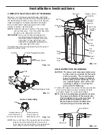
INSTALL VALVE DRAIN HOSE
NOTE: See valve drain options on pages 6 & 7.
1
. Measure, cut to needed length and connect the 9.5
mm drain line (provided) to the water treatment sys-
tem valve drain fitting. Use a hose clamp to hold
the hose in place.
IMPORTANT:
If codes require a rigid drain line see
“Valve Drain requirements" section.
2
. Run the drain hose (or a rigid line) to the floor drain.
Secure drain hose. This will prevent “whipping'' dur-
ing regenerations.
Be sure to provide a 4 cm min-
imum air gap to prevent possible sewer water
backup.
See “Air Gap Requirements" section.
NOTE:
In addition to a floor drain, you can use a laun-
dry tub or standpipe as a good drain point for
this hose.. Avoid long drain hose runs, or ele-
vating the hose more than 2.5 meters above
the floor.
INSTALL SALT STORAGE TANK OVERFLOW
HOSE
1
. Measure, cut to needed length and connect the 9.5
mm drain line (provided) to the salt storage tank
overflow elbow and secure in place with a hose
clamp.
2
Route the hose to the floor drain, or other suitable
drain point no higher than the drain fitting on the salt
storage tank (This is a gravity drain). If the tank
overfills with water, the excess water flows to the
drain point. Cut the drain line to the desired length
and route it neatly out of the way.
IMPORTANT:
For proper operation of the water treat-
ment system, do not connect the system
valve drain tubing to the salt storage
tank overflow hose.
ADD WATER AND SALT TO THE SALT
STOR AGE TANK
1
. Using a container, add about three gallons of clean
water into the salt storage tank.
2
. Add salt to the storage tank. Use nugget, pellet or
coarse solar salts with less than 1% impurities.
PLUG IN THE POWER SUPPLY
During installation, the water treatment system wiring
may be moved or jostled from place. Check to be sure
all leadwire connectors are secure on the back of the
electronic board and be sure all wiring is away from
the valve gear and motor area, which rotates during
regenerations.
1
. Plug the water softener’s power supply into an elec-
trical outlet that is not controlled by a switch and is
approved by local codes.
NOTE:
The water heater is filled with hard water and,
as hot water is used, it will refill with treated
water. In a few days, the hot water will be fully
treated. To have fully treated hot water imme-
diately, wait until the initial recharge is over.
Then, drain the water heater (following instruc-
tions for water heater) until water runs cold.
PROGRAM THE CONTROLLER
1
. Install the system’s top cover and salt lid.
2
. Complete the programming steps on pages 12 & 13.
RINSE OUT CARBON FINES
Small particles of carbon filtration material are generat-
ed during manufacturing and shipping, which will exit
the media tank with the first water flow. These carbon
“fines” are not harmful, but give the water a gray color
and should be rinsed down the drain before any water
from the system is directed to the home’s faucets or
water heater.
CAUTION:
To avoid water or air pressure damage to
system inner parts, and to flush pipe chips
or other residue from the water pipes, be
sure to do the following steps exactly as
instructed.
1
. Make sure the water treatment system’s valve drain
hose is hooked up and the open end directed to a
floor drain, laundry tub or other suitable type of
drain.
2
. The system should be connected to electrical power.
3
. Place bypass valve(s) in “bypass” position (see
Figures 7 & 8). On a single valve, slide the stem
inward to bypass. On a 3-valve bypass, close the
inlet and outlet valves and open the bypass valve.
4
. Fully open the house main water pipe shutoff valve.
5
. Initiate a regeneration by pressing and holding for 3
seconds the RECHARGE button (see Figure 16 on
page 12). The valve motor will start running and the
valve will advance to the “Fill” position.
6
. After you hear the valve motor stop running (valve
in “Fill” position), press, but do not hold, the
RECHARGE button. The valve will advance to the
“Brine” position.
continued on next page


