eCopy ScanStand Assembly Instructions
13
8.1
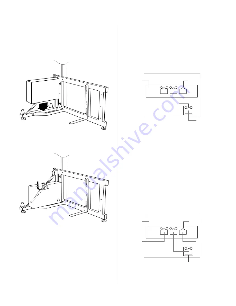
Slide stand into position behind copier. Allow
25-50 mm (1-2 inches) clearance between
frame and copier, taking care not to cover vents
or connectors.
8.2
Place PC on angle frame, connectors to rear,
leaving room to attach cable connectors.
8.3
Place PC clamp over PC, with short curved tip
engaging diagonal member of angle frame. The
clamp is held in place by its own weight.
8.4
Connect keyboard and screen cables to PC.
8.5
Attach power cable to PC.
8.6
Connect network cables as follows:
A. If there is a free network jack near the PC
:
Connect supplied long Ethernet cable from wall
jack to PC’s integrated network port. The internal
3-port hub is not used in this configuration.
This is the preferred configuration as it eliminates
the potential for printing interruptions if the
ScanStation is powered off.
B. If there is no free network jack
:
i. Remove copier’s network cable from wall jack
and connect it to left port on PC’s internal
3-port hub.
ii. Connect supplied long Ethernet cable from
network wall jack to uplink port on right of
internal 3-port hub.
iii. Connect supplied short Ethernet cable from
middle port of internal 3-port hub to PC’s
integrated network port.
In this configuration, the copier may fail to print if
the ScanStation PC goes into standby/hibernate
mode. To ensure this does not happen, disable
standby/hibernate mode as described on the next
page.
8.7
Complete setup of eCopy software (see the
eCopy software installation documentation for
details).
ScanStation PC
rear panel
Integrated network port
To wall jack
Internal
3-port hub
Uplink
port
ScanStation PC
rear panel
Integrated network port
To wall jack
Uplink
port
Internal
3-port hub
To copier
Step 8: PC configuration and software setup


