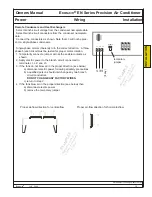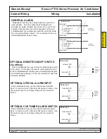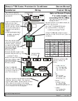
Ecosaire
®
EN Series Precision Air Conditioner Owners Manual
Installation Wiring Control Wiring
40
Ecosaire
®
July 2009
Data subject to change without notice.
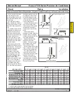
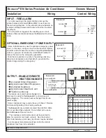
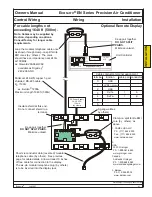
INPUT - FIRE ALARM
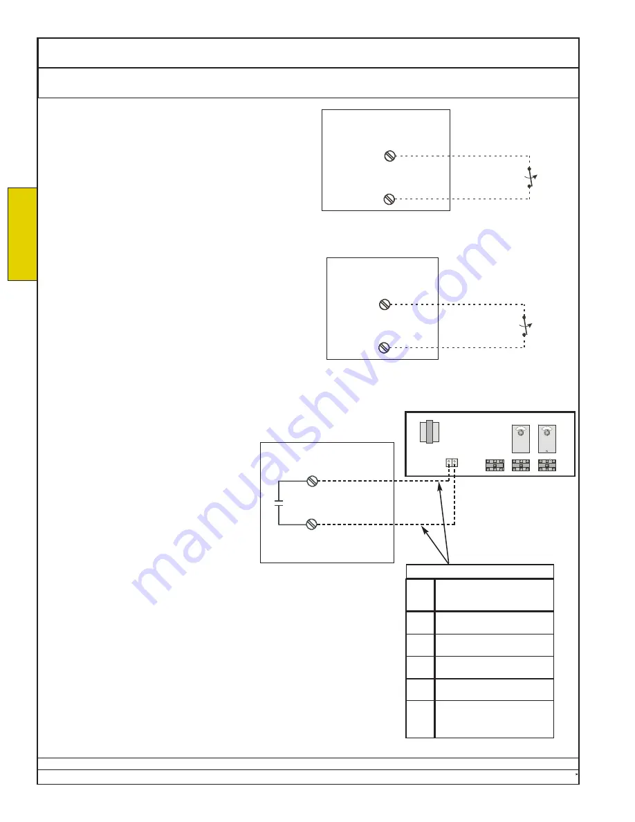
For units requiring a fire-alarm interlock, remove the
jumper between terminals
300
and
302
, or as shown on
the unit wiring diagram. In the jumper’s place substitute an
isolated normally-closed switch closure from the fire alarm
(by others).
If the fire alarm is triggered, the resulting open circuit
between these terminals will cause the
Ecosaire
® to shut-
down.
Fire alarm
or smoke
detector
switch
opens on
alarm.
terminal
300
terminal
302
Ecosaire
®
SAMPLE
Use terminal numbers in
unit wiring diagram.
OUTPUT - ENABLE REMOTE
HEAT EXCHANGER
••
Air-Cooled Direct-Expansion,
••
Glycol-Cooled Direct Expansion,
••
Air-Cooled DualCool,
••
Glycol-Cooled DualCool, and
••
FreeCool units only
The remote air-cooled heat-exchanger con-
trols must be wired to the
Ecosaire
® controls (see unit
wiring diagram). The remote heat exchanger has its own
power supply.
Some condensers may require the use of Class 1 Remote
Control and Signalling Circuit wiring methods.
The
Ecosaire
® dry contacts are rated 5A at 24VAC 60Hz.
Do not overload these outputs. Do not attempt to use an
internal
Ecosaire
® power source.
The condenser control-wire size must be selected to
allow for contactor coil inrush currents. See the chart at
right. Alternatively, a pilot relay (by others) may be installed.
In some cases temperature switches inside the remote
condenser may have to be adjusted.
wire
length Number of fan contactors
(ft)
1
2
3
4
5
6
10 20 20 20 20 20 18
20
20 20 20 20 18 14
30
20 20 20 20 18 14
40
20 20 20 18 16 12
50
20 20 20 18 14 10
60
20 20 20 16 14 10
70
20 20 18 16 14 10
80
20 20 18 16 12 10
90
20 20 18 16 12 10
100
20 20 18 14 12 10
110
20 20 16 14 12 10
Condenser control wire size (AWG)
xx
xx
remote heat exchanger
Ecosaire
®
terminal
J15-C8
terminal
J15-NO8
contacts close to
enable remote
heat exchanger
SAMPLE
Use terminal numbers in unit
wiring diagram.
OPTIONAL EMERGENCY POWER INPUT
Some installations may use the optional emergency power
input. In this case, an open circuit on the input will register
an alarm and will cause the number of operating
Ecosaire
®
units in a group to be reduced to a predefined number to
reduce the load on the emergency generator.
Note that a reduction in number of operating units may
allow room temperature and humidity to go outside the
desired range during the emergency.
terminal 300
terminal 314
Ecosaire
®
SAMPLE
Use terminal numbers in
unit wiring diagram.
Switch
opens to
cause
alarm
INST
ALLA
TION
Summary of Contents for EN Series
Page 1: ......
Page 103: ...OEM User manual ...
Page 104: ......
Page 106: ......
Page 108: ......
Page 110: ......
Page 123: ...OEM CAREL code 030221791 rel 2 1 21 09 07 15 4 2 Single phase wiring diagram INTERNAL TAM CP2 ...
Page 141: ......

