Owners Manual Ecosaire
®
EN Series Precision Air Conditioner
Control Wiring Wiring Installation
Ecosaire
®
July 2009 41
Data subject to change without notice.
INST
ALLA
TION
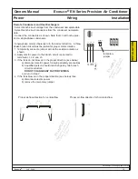
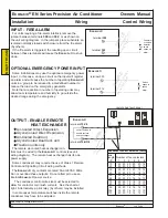
terminal 3
contacts close to
enable alarm
(by others)
terminal 4
GENERAL ALARM
E
cosaire
® units may be provided with an output for a
general alarm. Two dry-contact switch-closures are
provided to enable an alarm (by others) in the event of a
condition that prevents the normal operation of the unit.
The
Ecosaire
® dry contacts are rated 5A at 24VAC 60Hz.
Do not overload these outputs. Do not attempt to use an
internal
Ecosaire
® power source.
Ecosaire
®
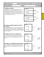
terminal 1
contacts close to
enable alarm
(by others)
to alarm
(by others)
terminal 2
SAMPLE
Use terminal numbers in
unit wiring diagram.
to alarm
(by others)
Ecosaire
®
OPTIONAL REMOTE ON/OFF SWITCH
(by others)
Some installations may use remote on/off switches provid-
ed by others. In this case the remote on/off switch must be
wired to the
Ecosaire
® controls (see unit field-wiring diagram
in unit information package). When dry contacts are open, the
unit will be disabled.
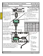
Switch
closes to
enable
unit.
terminal 300
terminal 301
SAMPLE
Use terminal numbers in
unit wiring diagram.
OPTIONAL SPECIAL ALARM INPUT
Some installations may use the optional special alarm
input. An open circuit on this input will cause an alarm. Use
dry contacts only, do not apply voltage from an external
source.
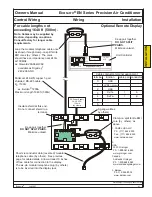
Switch
opens to
cause
alarm
terminal 300
terminal 313
Ecosaire
®
SAMPLE
Use terminal numbers in
unit wiring diagram.
OPTIONAL CUSTOMER ALARM SWITCH
Some installations may use the optional customer alarm
input. An open circuit on this input will cause an alarm. Use
dry contacts only, do not apply voltage from an external
source.
terminal 300
terminal 312
Ecosaire
®
SAMPLE
Use terminal numbers in
unit wiring diagram.
Switch
opens to
cause
alarm
Summary of Contents for EN Series
Page 1: ......
Page 103: ...OEM User manual ...
Page 104: ......
Page 106: ......
Page 108: ......
Page 110: ......
Page 123: ...OEM CAREL code 030221791 rel 2 1 21 09 07 15 4 2 Single phase wiring diagram INTERNAL TAM CP2 ...
Page 141: ......

