Installer manual ecoSMART
e-system
61
EN
NOTE
▪
Only use shielded three-wire cable. The use of any other cable may cause a malfunction of the
installation.
▪
Before any configuration make sure that the pLAN connector is disconnected. Failure to disconnect
the pLAN cable prior to configuration may result in installation malfunction and / or damage to the
heat pump components.
▪
Disconnect the pLAN cable if you need to update the e-system or the heat pump software.
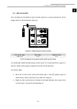
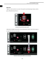
Illustration 3.8. Example of pLAN connection with the heat pump controller.
In addition to the connection of the heat pump, the
e-system
incorporates a BMS2 PORT
that allows communication with external devices as a slave of a Modbus network and a
Fieldbus1 to incorporate another measurement device into the inverter network in
special applications. These ports are free and its connection is not necessary for the
correct performance of the system. In case you want to connect an external device to
your
ecoSMART e-system
, contact ECOFOREST technical support before.
3.7. Digital control inputs (DIxx)
The
ecoSMART e-system
allows to wire up to four digital inputs for remote disconnection
of non-critical loads (from DI1 to DI4) and two digital inputs to enable the
“SMART GRID”
(DI6 and DI7) states. The electrical panel includes quick connectors for digital inputs.
NOTE
▪
The digital control inputs for both disabled non-critical loads and for determining the SG mode of
operation must be voltage-free inputs.
Tx
/R
x-
Tx
/R
x+
G
N
D
P
E
pLAN
N
O
1
N
C
1
J17
J16
C
1
O
u
t2
C
2
J18
O
u
t3
C
2
J19
O
u
t4
C
2
J20
O
u
t5
C
2
J21
C
2
V
-I
N
J22
N
O
6
C
6
J23
N
O
7
C
7
J24
N
O
8
C
8
N
O
9
C
9
J27
N
C
9
N
O
1
0
C
1
0
N
C
1
0
C
1
1
N
O
1
1
J28
N
O
1
2
N
O
1
3
C
1
1
J1
G
0
G
J2
U
2
U
1
U
3
G
N
D
J3
U
5
U
4
+V
d
c
+5
V
R
G
N
D
J4
U
7
U
6
+V
d
c
+5
V
R
G
N
D
J25
D
I7
D
I7
H
D
I7
C
D
I8
D
I8
H
J5
U
1
0
U
9
+V
d
c
+5
V
R
G
N
D
U
8
J6
Y2
Y1
Y3
G
N
D
J26
U
1
1
Y5
G
N
D
U
1
2
G
N
D
Y4
D
I9
D
I1
0
D
I9
C
J7
D
I3
D
I2
D
I4
G
N
D
D
I1
Tx
/R
x
-
Tx
/R
x+
G
N
G
J29
G
N
D
Tx
/R
x+
Tx
/R
x
-
J10 FBUS1
J15
G
N
D
Tx
/R
x+
Tx
/R
x
-
J11 BMS2
G
N
D
Tx
/R
x+
Tx
/R
x
-
J14 pLAN

