background image


06.11.2018 Rev. 08 

16 


Ø


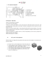
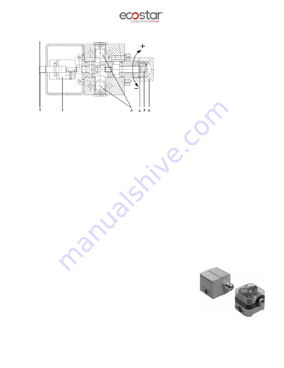
Oil Adjustment Regulator 


1- Connecting rod 
2- Scale coupler 
3- Fuel connection points 
4- Adjustment fixing bolt 
5- Adjustment bolt 
6- Housing cover (screw hood) 


Fuel Regulator Adjustment 

 
1-Remove the housing cover number 6 
2-Loosen the fixing bolt number 4 
3-When  you  rotate  the  shaft  number  5  (when  looked  from  the  shaft  end)  clockwise,  the  pressure  value 
you observe from return manometer will increase, and burner consumption will also increase since nozzle 
pressure increases.  
4-When  you  rotate  the  shaft  number  5  (when  looked  from  the  shaft  end)  anti-clockwise,  the  pressure 
value you observe from return manometer will decrease, and burner consumption will also decrease since 
nozzle pressure decreases. 
5-When  the  adjustment  is  completed;  make  sure  that  the  adjustment  you  have  made  is  permanent  by 
tightening the fixing bolt number 4.  
6-Place the housing cover number 6. 


6.3.


Air Pressure Switch Adjustment 


While the burner is working without any problem, the air pressure switch is adjusted to desired minimum 
pressure as follows. 


Ø


Unscrew the screw of the transparent cover and remove the cover. 

Ø


Turn the adjustment wheel in the direction to increase the pressure, 
note the pressure value at which the burner is failed. 

Ø


Set the pressure switch to a value 1 mbar lower than the pressure 
value at which the burner failed and close the pressure switch lid. 

Ø


It is recommended that this adjustment is carried out when the 
burner is at minimum load. 


Summary of Contents for ECO 300

Page 1: ...ev 08 www ecostar com tr DUOBLOCK DUAL FUEL GAS HEAVY OIL BURNERS INSTALLATION OPERATING AND MAINTENANCE MANUAL MODULATING OPERATION ECO 250 ECO 300 ECO 350 ECO 400 ECO 450 ECO 500 ECO 600 ECO 700 ECO...

Page 2: ...you encounter any issue that is not explained clearly in this manual or you could not understand please contact with our service department We thank you for choosing ECOSTAR brand Ecostar Dual Fuel Ga...

Page 3: ...r Dimensions 10 5 INSTALLATION 11 5 1 Burner Installation Picture 11 6 COMMISSIONING 12 6 1 General Controls 12 6 2 Combustion Adjustment 13 6 3 Air Pressure Switch Adjustment 16 6 4 Servomotor Adjust...

Page 4: ...ectrical voltage Product handling information PF Impulse connection detecting combustion chamber pressure PL Impulse connection detecting combustion air pressure PBR Impulse connection detecting burne...

Page 5: ...epairs concerned with safety elements should be carried out only by the manufacturing company The device should never be used by children mentally handicapped and inexperienced persons Children must n...

Page 6: ...mper connections must be checked to ensure that they are free running in spite of immobility and oil freezing In case of two piece flame tubes of ECO 450 and upper combined burner models being demount...

Page 7: ...roduct in its original packaging until the installation stage Incorrect and poor electrical connections Failures due to incorrect voltage applications frequent repetition of voltage fluctuations Any d...

Page 8: ...d burner pressure ranges 3 1 Purpose of Use and Work Limits of Burners This product works at any load value equivalent to its max capacity or covered by its capacity range In hot water and steam boile...

Page 9: ...06 11 2018 Rev 08 8 Temperature change of fuel used in ECOSTAR Dual Fuel Gas Heavy Oil burners dependent on viscosity...

Page 10: ...509 1 1290 2 ECO 500 1 16 2 13 900 000 1684 8 1440 4 ECO 500 2 17 8 15 300 000 1854 5 1585 5 ECO 500 3 19 4 16 650 000 2018 2 1725 4 ECO 600 1 20 8 17 900 000 2169 7 1854 9 ECO 600 2 23 4 20 150 000 2...

Page 11: ...06 11 2018 Rev 08 10 4 2 Burner Dimensions...

Page 12: ...use the installation materials supplied with the burner Make sure that there are no gaps between the flange and boiler cover and ensure a full sealing by a gasket Make sure that when installing burne...

Page 13: ...and combustion will occur Flame control system will start to flame control In modulating burner the burner goes into max capacity according to the signal from the modulating control unit When the boil...

Page 14: ...13 6 2 Combustion Adjustment Photocell Check the photocell weekly Clean the dust or fume stains on the glass of photocell by a dry cloth QRA10 QRA2 Pilot Ignition System Pilot gas burner inlet pressu...

Page 15: ...2018 Rev 08 14 HA D Nozzle 32 HA D is a needle closed lance with return line Shut down needle 4 make press to nozzle plate 6 through a spiral on pushing piston Shut down needle is opened by pneumatic...

Page 16: ...06 11 2018 Rev 08 15 HA D Nozzle Hydraulic Diagram...

Page 17: ...er will decrease and burner consumption will also decrease since nozzle pressure decreases 5 When the adjustment is completed make sure that the adjustment you have made is permanent by tightening the...

Page 18: ...d CO 100 mg kWh 3 O2 5 NOx 170 mg kWh Excess air ratio 1 2 1 3 In emission measurements the following values are accepted as reference according to TS EN 267 standard CO 110 mg kWh 3 O2 5 NOx 250 mg k...

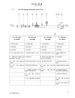
Page 19: ...nlet manometer valve 8 Multi block safety and operation solenoids 5 Regulator 8 Multi block safety and operation solenoids 5 Regulator 10 max gas pressure switch 6 Outlet manometer valve 9 Sealing Con...

Page 20: ...ent possible faults After completion of maintenance and adjustment processes make sure to perform a combustion analysis Clean the filters on the fuel line to the burner Clean fuel nozzle of the burner...

Page 21: ...of electric motor Make surface cleaning of ignition electrodes and porcelains Replace cracked or broken porcelains Clean air fan and clamps Check the operating function Check cleanliness of the nozzl...

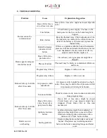
Page 22: ...tocell may be faulty or contaminated Remove and clean Program relay failure Replace it with a new one Burner starts up but fails after 10 seconds Program relay failure Replace it with a new one Air pr...

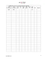
Page 23: ...06 11 2018 Rev 08 22 9 PERIODICAL FLUE GAS MEASUREMENT REPORT Fuel Consumption kg h Fuel Consumption m3 h CO ppm O2 CO2 ppm NOX ppm Yield Flue Temp C Date Signature...

Page 24: ...T RK YE Tel 90 216 442 93 00 Fax 90 216 370 45 03 Factory Contact Details T rkg c OSB B lent Ecevit Bulvar No 11 ORLU TEK RDA T RK YE Tel 90 282 685 44 80 81 Fax 90 282 685 42 09 Also you can contact...

Page 25: ...06 11 2018 Rev 08 24 11 NOTES Please record and forward your measurements and observations to us www ecostar com tr...

Reviews: