09.06.2017 Rev. 08
41
COMMISSIONING
Before Commissioning
Electrical Connection
Perform electrical connections according to the diagram provided with the burner. Follow general
security rules during installation of electric wiring and making connections. Connect the earthing terminal
in electric panel to the earthing installation.
General Controls
Make sure to perform the following controls before commissioning the burner.
Ø
Installation of the burner to the boiler is checked.
Ø
Check the fuel line (are the pipe diameters and the pipe installation correct?).
Ø
Check energy input cables and voltages.
Ø
Check the boiler safety thermostats and, if it is a two-stage burner, then make sure that there are
two thermostats.
Ø
Check the fuel nozzles according to the boiler capacity.
Ø
Prior to operating the burner, control the boiler water level.
Ø
Make sure water circulation system is turned on, and steam boiler and water feed pumps and
boiler inlet - outlets are open.
Ø
Is there electricity current?
Ø
Is there gas?
Ø
Has the boiler explosion lid been controlled?
Ø
Is there sufficient air in boiler room (ventilation section cm² = boiler capacity kW x 7)
Ø
Has the air of the gas line been removed? Has a sealing test been made?
Commissioning order
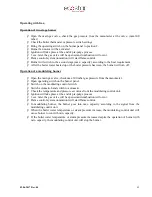
Operating with Light Oil ;
Ø
After performing the above mentioned controls, open the fuel tank valve.
Ø
Open the valve upstream of the fuel filter.
Ø
Check direction of motor rotation.
Ø
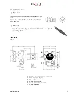
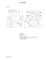
Open the pump’s vent plug and place the manometer (0-40 bar).
Ø
Turn on the burner switch (turn to position 1).
Ø
When the burner starts up, the motor is activated and turns the pump at the same time.
Ø
It actuates pre-purge and discharges the residual gases remaining in the boiler from the funnel.
Ø
After the pre-purge, fuel is delivered from the nozzle. The fuel meets the flame from the ignition
electrodes and the combustion starts.
Ø
After combustion of the burner, the pump pressure is adjusted (light oil: two stage; 14 bar,
modulating; 25 bar).
Ø
If the burner has two stages, the switch is brought to position “2”, and the capacity of the burner is
increased through servomotor. Ideal combustion is obtained by increasing the amount of air by the
fuel given according to analyses value.
Ø
The boiler thermostat is adjusted as desired (70-90°C for central heating boilers).
Ø
For the safety of the system, check the boiler thermostats and observe the deactivation of the
burner.
Summary of Contents for ECO 50 K L C 2
Page 10: ...09 06 2017 Rev 08 9 Burner Components ECO 50 KLC2...
Page 12: ...09 06 2017 Rev 08 11 ECO 55 KLC2 2a...
Page 14: ...09 06 2017 Rev 08 13 ECO 60 KLC2...
Page 16: ...09 06 2017 Rev 08 15 ECO 65 KLC2...
Page 18: ...09 06 2017 Rev 08 17 ECO 70 KLC2...
Page 20: ...09 06 2017 Rev 08 19 ECO 50 KLC3...
Page 22: ...09 06 2017 Rev 08 21 ECO 55 KLC3 3a...
Page 24: ...09 06 2017 Rev 08 23 ECO 60 KLC3...
Page 26: ...09 06 2017 Rev 08 25 ECO 65 KLC3...
Page 28: ...09 06 2017 Rev 08 27 ECO 70 KLC3...
Page 30: ...09 06 2017 Rev 08 29 ECO 75 KLC3...
Page 33: ...09 06 2017 Rev 08 32 Back Pressure Capacity Diagrams...
Page 34: ...09 06 2017 Rev 08 33 Burner Dimensions...
Page 36: ...09 06 2017 Rev 08 35...
Page 37: ...09 06 2017 Rev 08 36...
Page 49: ...09 06 2017 Rev 08 48 MB ZRD LE 405 412 Series Gas Valve...
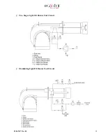
Page 58: ...09 06 2017 Rev 08 57 Light Oil Burner Fuel Ring Line...


