09.06.2017 Rev. 08
53
5 -
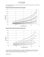
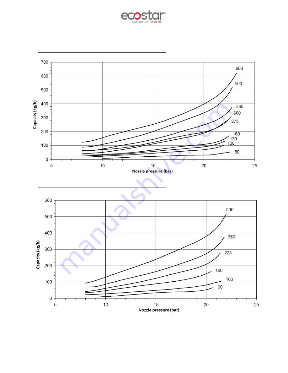
Set the burner to the correct capacity required by the boiler by considering the below nozzle pressure
and consumption values.
Diagram valid for fuel nozzles having 45° spraying angle
Diagram valid for fuel nozzles having 60° spraying angle
6 –
Once the burner modulating adjustment is completed, set modulating control device to automatic
position, change set values and observe capacity changes. Air and fuel will increase and decrease
simultaneously according to the adjustment you previously made.
Summary of Contents for ECO 50 K L C 2
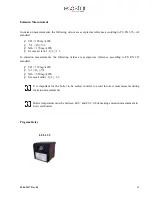
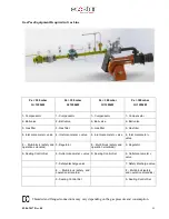
Page 10: ...09 06 2017 Rev 08 9 Burner Components ECO 50 KLC2...
Page 12: ...09 06 2017 Rev 08 11 ECO 55 KLC2 2a...
Page 14: ...09 06 2017 Rev 08 13 ECO 60 KLC2...
Page 16: ...09 06 2017 Rev 08 15 ECO 65 KLC2...
Page 18: ...09 06 2017 Rev 08 17 ECO 70 KLC2...
Page 20: ...09 06 2017 Rev 08 19 ECO 50 KLC3...
Page 22: ...09 06 2017 Rev 08 21 ECO 55 KLC3 3a...
Page 24: ...09 06 2017 Rev 08 23 ECO 60 KLC3...
Page 26: ...09 06 2017 Rev 08 25 ECO 65 KLC3...
Page 28: ...09 06 2017 Rev 08 27 ECO 70 KLC3...
Page 30: ...09 06 2017 Rev 08 29 ECO 75 KLC3...
Page 33: ...09 06 2017 Rev 08 32 Back Pressure Capacity Diagrams...
Page 34: ...09 06 2017 Rev 08 33 Burner Dimensions...
Page 36: ...09 06 2017 Rev 08 35...
Page 37: ...09 06 2017 Rev 08 36...
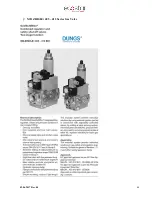
Page 49: ...09 06 2017 Rev 08 48 MB ZRD LE 405 412 Series Gas Valve...
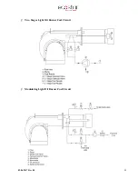
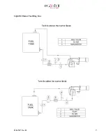
Page 58: ...09 06 2017 Rev 08 57 Light Oil Burner Fuel Ring Line...


