background image


EP_Ecotech_Serinus30_en.docx 


www.umwelt-tuv.de 


    teu-service@de.tuv.com


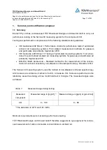
The department of Environmental Protection of TÜV Rheinland Energie und Umwelt GmbH  

is accredited for the following work areas: 


Determination of air quality and emissions of air pollution and odour substances;  

Inspection of correct installation, function and calibration of continuously operating emission measuring instru-

ments, including data evaluation and remote emission monitoring systems; 

Combustion chamber measurements; 

Performance testing of measuring systems for continuous monitoring of emissions and ambient air, and of elec-

tronic data evaluation and remote emission monitoring systems; 

Determination of stack height and air quality projections for hazardous and odour substances; 

Determination of noise and vibration emissions and pollution, determination of sound power levels and execu-

tion of sound measurements at wind energy plants 


according to EN ISO/IEC 17025. 


The accreditation is valid up to 22-01-2018. DAkkS-register number: D-PL-11120-02-00. 


Reproduction of extracts from this test report is subject to written consent. 


TÜV Rheinland Energie und Umwelt GmbH 

D - 51105 Cologne, Am Grauen Stein, Tel: +49 221 806-2756. Fax: +49 221 806-1349 


TÜV RHEINLAND  

ENERGIE UND UMWELT GMBH 


Report  on  the  performance  testing  of  the  Ser-

inus 30  ambient  air  quality  monitoring  system 

manufactured by Ecotech Pty Ltd measuring CO 


TÜV Report:  936/21221977/D_EN 

Cologne,  08 October 2013 


Summary of Contents for Serinus 30

Page 1: ...tion and remote emission monitoring systems Determination of stack height and air quality projections for hazardous and odour substances Determination of noise and vibration emissions and pollution de...

Page 2: ...ir Pollution Control Page 2 of 253 Report on the performance testing of the Serinus 30 ambient air quality moni toring system manufactured by Ecotech Pty Ltd measuring CO Report no 936 21221977 D_EN E...

Page 3: ...ng of the Serinus 30 ambient air quality monitoring system manufactured by Ecotech Pty Ltd measuring CO Instrument tested Serinus 30 Manufacturer Ecotech Pty Ltd 1492 Ferntree Gully Road Knoxfield VIC...

Page 4: ...ir Pollution Control Page 4 of 253 Report on the performance testing of the Serinus 30 ambient air quality moni toring system manufactured by Ecotech Pty Ltd measuring CO Report no 936 21221977 D_EN E...

Page 5: ...esults 13 2 TASK DEFINITION 22 2 1 Nature of the test 22 2 2 Objective 22 3 DESCRIPTION OF THE ANALYSER TESTED 23 3 1 Measuring principle 23 3 2 Analyser scope and set up 26 4 TEST PROGRAMME 33 4 1 Ge...

Page 6: ...standard deviation at zero point 54 6 1 5 3 3 Repeatability standard deviation at span point 55 6 1 5 3 4 Linearity lack of fit 56 6 1 5 3 5 Sensitivity coefficient of sample gas pressure 57 6 1 5 3...

Page 7: ...4 7 Sensitivity coefficient to sample gas pressure 87 7 1 8 4 8 Sensitivity coefficient to sample gas temperature 89 7 1 8 4 9 Sensitivity coefficient to the surrounding temperature 91 7 1 8 4 10 Sen...

Page 8: ...rmination of the influence of sample gas temperature for NO 90 Table 18 Sensitivity coefficient to the surrounding temperature at zero point and at span point systems 1 and 2 92 Table 19 Individual re...

Page 9: ...omponents of the Serinus 30 measuring system 26 Figure 5 Internal view of the Serinus 30 measuring system 27 Figure 6 Pneumatic circuit diagram of the Serinus 30 measuring system 31 Figure 7 Rear pane...

Page 10: ...ir Pollution Control Page 10 of 253 Report on the performance testing of the Serinus 30 ambient air quality monitoring system manufactured by Ecotech Pty Ltd measuring CO Report no 936 21221977 D_EN E...

Page 11: ...Sheet 3 Testing of automated measuring systems Test proce dures for point related ambient air measuring systems for gaseous and particulate air pollutants September 2010 DIN EN 14626 Ambient air Stan...

Page 12: ...tem AMS designation Serinus 30 for CO Manufacturer Ecotech Pty Ltd Knoxfield Australia Field of application Continuous measurement of carbon monoxide concentrations in ambient air from stationary sour...

Page 13: ...be applied in the corresponding sub tests and included in the assess ment The tested instrument does not have an internal device for functional checks not ap plicable 38 4 1 4 Set up times and warm u...

Page 14: ...signals May not be suppressed life ze ro The measuring system also displays negative measured values yes 46 5 2 4 Failure in the mains voltage In case of malfunction of the measuring system or failur...

Page 15: ...012 yes 53 5 3 2 Repeatability standard deviation at zero point The repeatability standard de viation at zero point shall not exceed the requirements listed in Table 1 of VDI Guide line 4202 Sheet 1 S...

Page 16: ...coefficient of surrounding tem perature The sensitivity coefficient of surrounding temperature at ze ro and reference point shall not exceed the requirements listed in Table 2 of VDI Guideline 4202 Sh...

Page 17: ...DI Guideline 4202 Sheet 1 Sep tember 2010 Please refer to section 7 1 8 5 5 Reproducibility standard deviation for CO under field conditions yes 63 5 3 12 Long term drift The long term drift at zero p...

Page 18: ...tems the increase of NO2 con centration due to residence in the measuring system shall not exceed the requirements listed in Table 2 of VDI Guideline 4202 Sheet 1 September 2010 Not applicable as the...

Page 19: ...nt The repeatability standard deviation at zero point is 0 02 mol mol for sys tem 1 and 0 02 mol mol for system 2 The repeatability standard devia tion at span point is 0 03 mol mol for system 1 and 0...

Page 20: ...ivity coefficient to electrical voltage shall not ex ceed 0 30 mol mol V i e 0 35 mg m V The sensitivity coefficient of electrical voltage bv does not exceed the per formance criteria of max 0 30 mol...

Page 21: ...ong term drift at span lev el shall not exceed 5 of the certification range i e 4 3 mol mol in a measuring range of 0 to 86 mol mol The maximum long term drift at zero Dl z is 0 23 mol mol for system...

Page 22: ...noxide 0 100 mg m The Serinus 30 uses the method of non dispersive infrared spectroscopy to measure CO Performance testing was to be carried out in accordance with current standards taking into consid...

Page 23: ...following components microprocessor control proven Gas Filter Correlation Gfc combined with Non Dispersive Infrared Spectrophotometry NDIR technology The CO concentration is automatically corrected f...

Page 24: ...mg m3 d is the optical path length in m Figure 2 Illustration of the theoretical measurement method within the cell The system includes a gas filter correlation wheel It contains three parts which imp...

Page 25: ...ung Report on the performance testing of the Serinus 30 ambient air quality moni toring system manufactured by Ecotech Pty Ltd measuring CO Report no 936 21221977 D_EN Page 25 of 253 EP_Ecotech_Serinu...

Page 26: ...s30_en docx 3 2 Analyser scope and set up The carbon monoxide analyser consists of five main modules pneumatics for passing on sample and exhaust gas sensors for measuring carbon monoxide optical cell...

Page 27: ...Teflon 5 micron m filter with a diameter of 47 mm This filter elim inates all particles larger than 5 m that could interfere with sample measurement CO CO2 converter The CO CO2 catalytic converter us...

Page 28: ...aligned through the correlation wheel Measurement cell The measurement cell contains 5 mirrors which help to generate a path length of 5 metres through the cell The sample gas fills the cell and the...

Page 29: ...cess and real time access to instruments when a network is available to connect with External I O Port The analogue digital port sends and receives analogue digital signal to from other devices These...

Page 30: ...977 D_EN EP_Ecotech_Serinus30_en docx Sample gas pump Manufacturer Thomas type 617CD22 194 C During performance testing the above mentioned sample gas pump was used in the labora tory as well as in th...

Page 31: ...ality moni toring system manufactured by Ecotech Pty Ltd measuring CO Report no 936 21221977 D_EN Page 31 of 253 EP_Ecotech_Serinus30_en docx Figure 6 Pneumatic circuit diagram of the Serinus 30 measu...

Page 32: ...grammable Units ppb ppm mg m mg m Measured compounds CO Sample flow rate approx 1 litre min Output signals USB port on the back side Bluetooth digital communication via Android Application TCP IP Ethe...

Page 33: ...ng for each test criterion along with the number and description as stipulated in the respective standard 1 2 3 4 4 2 Laboratory test The laboratory test was carried out with two identical Serinus 30...

Page 34: ...The field test was carried out with two complete and identical Serinus 30 measuring systems and lasted from 04 July 2013 04 October 2013 The measuring systems under test were identical to those used...

Page 35: ...re test and where necessary diluted with the help of a sample divider or a mass flow control station Zero gas Synthetic air Test gas CO 254 ppm in synth air Number of test gas cylinder 15675 Manufactu...

Page 36: ...3 6 1 4 1 1 Measured value display The measuring system shall be fitted with a measured value display 6 2 Equipment No additional equipment is required 6 3 Testing It was checked whether the measurin...

Page 37: ...maintenance tasks 1 Checking of the instrument status The status of the instrument can be checked and monitored by way of visual inspec tion of the display 2 Checking and replacing the particulate fi...

Page 38: ...te control via the measuring system 6 2 Equipment Manual 6 3 Testing The tested instrument does not have an internal device for functional checks The operation al status of the AMS is continually moni...

Page 39: ...specific conditions of the measurement site as well as on the voltage supply available As the Serinus 30 measuring system is a compact analyser the set up time is mainly comprised of Establishing the...

Page 40: ...vided instruments was compared to the description in the instruction manuals The power consumption was determined for 24 h during normal operation in the field test 6 4 Evaluation The measuring system...

Page 41: ...anging parameters or adjusting sen sors is only possible by pushing several sequences of keys As the system may not be set up outside protection against unintended or unauthorised re adjustment will h...

Page 42: ...er it has a means to output analogue signals max 3 analogue outputs 6 4 Evaluation Measured signals are output at the back of the system as follows Analogue 0 20 2 20 4 20 mA or 0 5 V selectable conce...

Page 43: ...etter than the results of the performance test 6 2 Equipment No additional equipment is required to test this criterion 6 3 Testing The test results were compared to the specifications in the instruct...

Page 44: ...ded for testing shall be determined 6 4 Evaluation VDI Guideline 4202 Sheet 1 and Standard DIN EN 14626 stipulate the following minimum requirements for the certification ranges of continuous ambient...

Page 45: ...6 3 Testing It was determined whether the upper limit of the measuring range was greater or equal to the upper limit of the certification range 6 4 Evaluation In principle the measuring system allows...

Page 46: ...easured values may not be suppressed life zero 6 2 Equipment No additional equipment is required to test this performance criterion 6 3 Testing It was tested in the laboratory and in the field whether...

Page 47: ...he instrument re mains intact and is ready to measure when mains voltage returns 6 4 Evaluation The measuring system does not require any operation or calibration gases Thus there is no uncontrolled e...

Page 48: ...tion of the analyser and by choosing the menu item Remote Screen the analyser display is shown on the connected PC In this mode all information and functions shown on the analyser dis play can be acce...

Page 49: ...quipment is required to test this performance criterion 6 3 Testing The measuring system may be monitored or controlled via the control panel of the analyser or telemetrically via remote control 6 4 E...

Page 50: ...corresponding maintenance intervals needed to ensure proper functioning of the measuring system were determined Moreover drift behaviour of zero span point according to 7 1 8 5 4 Long term drift was t...

Page 51: ...ite To this effect any interruptions of the test for instance due to malfunctions or maintenance work are recorded 6 4 Evaluation The field test was carried out in the period from 04 July 2013 to 04 O...

Page 52: ...required to test this performance criterion 6 3 Testing It was verified whether the instrument displays its current software version upon switch on The instrument manufacturer was advised to inform t...

Page 53: ...sting The test is performed on the basis of the minimum requirements as stipulated in VDI 4202 Sheet 1 September 2010 and Standard DIN EN 14626 December 2012 6 4 Evaluation VDI Guideline 4202 Sheet 1...

Page 54: ...andard deviation at zero point shall not exceed 2 of the upper limit of this certification range The repeatability standard deviation at zero point shall not exceed 1 0 mol mol i e 1 16 mg m 6 2 Equip...

Page 55: ...t span point shall not exceed 2 of the upper limit of this certification range In this case a value ct at 70 to 80 of the upper limit of this certification range shall be used as span point The repeat...

Page 56: ...1 September 2010 For all other certification ranges the group averages of measured values about the calibration function shall not exceed 5 of the upper limit of the corresponding cer tification range...

Page 57: ...ference point The sensitivity coefficient of sample gas pressure shall not exceed 0 7 mol mol kPa i e 0 81 mg m kPa 6 2 Equipment Not applicable here 6 3 Testing Performance and evaluation of the step...

Page 58: ...r ence point The sensitivity coefficient of sample gas temperature shall not exceed 0 3 mol mol K i e 0 35 mg m K 6 2 Equipment Not applicable here 6 3 Testing Performance and evaluation of the steps...

Page 59: ...e point The sensitivity coefficient of surrounding temperature shall not exceed 0 3 mol mol K i e 0 35 mg m K 6 2 Equipment Not applicable here 6 3 Testing Performance and evaluation of the steps take...

Page 60: ...e point The sensitivity coefficient of supply voltage shall not exceed 0 3 mol mol V i e 0 35 mg m V 6 2 Equipment Not applicable here 6 3 Testing Performance and evaluation of the steps taken to dete...

Page 61: ...te values of the sum of the positive and the sum of negative deviations caused by interfering com ponents in the sample gas shall not exceed 3 of the upper limit of the certification range at zero and...

Page 62: ...uirements of Table 2 of VDI 4202 Sheet 1 September 2010 The averaging effect shall not exceed 7 of the measured value 6 2 Equipment Not applicable here 6 3 Testing Performance and evaluation of the st...

Page 63: ...viation under field conditions shall not exceed 5 of the average over a period of 3 months 6 2 Equipment Not applicable here 6 3 Testing Performance and evaluation of the steps taken to determine the...

Page 64: ...be used at refer ence point The long term drift at zero shall not exceed 0 5 mol mol i e 0 58 mg m The long term drift at span point shall not exceed 5 of the upper limit of the certifi cation range...

Page 65: ...upper limit of the certification range shall be used as reference point The short term drift at zero point shall not exceed 0 1 mol mol i e 0 12 mg m The short term drift at span point shall not exce...

Page 66: ...he response time rise and response time fall of the measuring system shall not exceed 10 of response time rise or 10 s whatever value is larger 6 2 Equipment Not applicable here 6 3 Testing Performanc...

Page 67: ...it of the certi fication range shall be used as reference point The difference between sample and calibration port shall not exceed 1 6 2 Equipment Not applicable here 6 3 Testing Performance and eval...

Page 68: ...cy In case of measuring systems with a converter the converter efficiency shall be at least 98 6 2 Equipment Not applicable here 6 3 Testing Due to the measurement principle the tested measuring syste...

Page 69: ...uirements of Table 2 of VDI 4202 Sheet 1 September 2010 The requirements of Table 2 of VDI 4202 Sheet 1 September 2010 apply to certi fication ranges according to Table 1 of VDI 4202 Sheet 1 September...

Page 70: ...2 Equipment Not applicable here 6 3 Testing The determination of uncertainty was performed in accordance with DIN EN 14626 2012 and is detailed in section 7 1 8 6 Total uncertainty in accordance with...

Page 71: ...n gas shall be chosen in such a way that the dead time in the valve and tee can be neglected compared to the lag time of the analyser system The step change is made by switching the valve from ze ro g...

Page 72: ...eport no 936 21221977 D_EN EP_Ecotech_Serinus30_en docx Figure 9 Diagram illustrating the response time 7 3 Testing The test was performed in accordance with the requirements on testing as stipulated...

Page 73: ...stems for CO For system 1 this results in a maximum tr of 50 s a maximum tf of 52 s and a td of 2 s for CO For system 2 this results in a maximum tr of 51 s a maximum tf of 56 s and a td of 5 s for CO...

Page 74: ...lta t 00 00 56 00 00 52 delta t s 56 52 Cycle 3 t 0 14 12 00 14 12 53 14 13 05 14 18 00 14 18 54 14 19 27 delta t 00 00 53 00 00 54 delta t s 53 54 Cycle 4 t 0 14 26 00 14 26 53 14 27 40 14 33 00 14 3...

Page 75: ...atory conditions while analysing ambient air After a period of 12 h zero and span gas is fed to the analyser After waiting the time equivalent to one independent reading 20 individual measurements are...

Page 76: ...readings obtained for the short term drift Table 7 Results for the short term drift 7 5 Assessment The short term drift at zero is 0 01 mol mol for system 1and 0 08 mol mol for system 2 The short ter...

Page 77: ...00 65 2 64 5 06 40 00 0 1 0 1 07 11 00 65 2 64 5 06 41 00 0 1 0 1 07 12 00 65 2 64 5 06 42 00 0 1 0 1 07 13 00 65 2 64 5 06 43 00 0 1 0 1 07 14 00 65 2 64 5 06 44 00 0 1 0 1 07 15 00 65 2 64 5 06 45 0...

Page 78: ...07 00 65 3 64 7 18 38 00 0 1 0 1 19 08 00 65 3 64 7 18 39 00 0 1 0 1 19 09 00 65 3 64 7 18 40 00 0 1 0 1 19 10 00 65 3 64 7 18 41 00 0 1 0 1 19 11 00 65 3 64 7 18 42 00 0 1 0 1 19 12 00 65 3 64 7 18 4...

Page 79: ...in mol mol i x is the ith measurement in mol mol x is the average of the 20 measurements in mol mol n is the number of measurements n 20 The repeatability standard deviation shall be calculated separa...

Page 80: ...he repeatability standard deviation Table 10 Repeatability standard deviation at zero and span point 7 5 Assessment The repeatability standard deviation at zero point is 0 02 mol mol for system 1 and...

Page 81: ...9 2 9 6 13 06 51 0 1 0 1 12 33 50 9 2 9 6 13 07 46 0 1 0 1 12 34 45 9 2 9 6 13 08 41 0 1 0 1 12 35 40 9 2 9 6 13 09 36 0 0 0 1 12 36 35 9 2 9 6 13 10 31 0 0 0 1 12 37 30 9 2 9 6 13 11 26 0 0 0 1 12 3...

Page 82: ...ments shall be performed The concentrations shall be applied in the following sequence 80 40 0 60 20 and 95 After each change in concentration at least four response times shall be taken in to account...

Page 83: ...point including the zero point at one and the same concentration c is calculated according to m Y Y c i c a where Ya c is the average Y value at a concentration level c Yi c is the individual Y value...

Page 84: ...function for CO Figure 10 Function established from group averages for system 1 component CO Requirement 4 0 0 86 0 93 0 5 0 10 0 00 Residual at zero rz mol mol Largest value of the relative residual...

Page 85: ...than zero For system 2 the deviation from the regression line is 0 04 mol mol at zero point and max 0 93 of the target value for concentrations greater than zero Deviations from the ideal regression l...

Page 86: ...01 56 40 34 32 34 48 34 81 34 48 11 02 51 40 34 32 34 48 34 81 34 48 11 03 46 40 34 32 34 48 34 81 34 48 11 04 41 40 34 32 34 48 34 81 34 48 11 16 01 0 0 05 0 00 0 03 0 00 11 16 56 0 0 10 0 00 0 05 0...

Page 87: ...1 2 P P C C b P P gp where gp b is the sample gas pressure sensitivity coefficient in mol mol kPa 1 P C is the average concentration of the measurements at sampling gas pressure P1 in mol mol 2 P C i...

Page 88: ...le gas pressure is 0 04 mol mol kPa For system 2 the sensitivity coefficient to sample gas pressure is 0 03 mol mol kPa Does this comply with the performance criterion yes 7 6 Detailed presentation of...

Page 89: ...ge concentration of the measurements at sample gas temperature TG 1 in mol mol K 2 GT C is the average concentration of the measurements at sample gas temperature TG 2 in mol mol K 1 G T is the minimu...

Page 90: ...ensitivity coefficient to sample gas temperature is 0 00 mol mol K Does this comply with the performance criterion yes 7 6 Detailed presentation of test results Table 17 Individual values obtained fro...

Page 91: ...Tl and Tl Tmax Tl At the first temperature Tl the analyser shall be adjusted at zero and at span level 70 to 80 of the maximum of the certification range Then three individual measurements are record...

Page 92: ...surrounding temperature resulted from the tests Table 18 Sensitivity coefficient to the surrounding temperature at zero point and at span point systems 1 and 2 As illustrated in Table 18 the sensitivi...

Page 93: ...Date Time Temp C mol mol mol mol Time Temp C mol mol mol mol 13 05 2013 16 17 41 20 0 0 0 3 16 32 37 20 65 6 65 8 13 05 2013 16 18 37 20 0 0 0 3 16 33 33 20 65 6 65 8 13 05 2013 16 19 33 20 0 0 0 3 1...

Page 94: ...C C b V V v where v b is the voltage sensitivity coefficient in mol mol V 1 V C is the average concentration reading of the measurements at voltage V1 in mol mol 2 V C is the average concentration rea...

Page 95: ...mol V and for system 2 it is 0 001 mol mol V Does this comply with the performance criterion yes 7 6 Detailed presentation of test results Table 21 Individual results for the tests of the sensitivity...

Page 96: ...on effect due to addition of an interferent e g wa ter vapour After adjustment of the analyser at zero and span level the analyser shall be fed with a mix ture of zero gas and the interferent to be in...

Page 97: ...at the limit value ct is 0 10 mol mol for system 1 and 0 11 mol mol for system 2 for the component H2O 0 00 mol mol for system 1 and 0 05 mol mol for system 2 for the component CO2 0 11 mol mol for sy...

Page 98: ...11 14 09 12 11 09 8 49 8 49 9 19 9 25 11 17 00 12 15 54 8 49 8 49 9 19 9 25 11 20 48 12 19 42 8 49 8 49 9 19 9 25 Average xct 8 49 8 49 9 19 9 25 12 24 42 12 47 30 0 00 0 01 0 00 0 08 12 27 33 12 50...

Page 99: ...n zero and a concentration ct similar to the 8 hour limit value 8 6 mol mol The time period tc of the constant CO concentration shall be at least equal to a period nec essary to obtain four independen...

Page 100: ...First the average was calculated at a constant concentration of test gas Then an alternating change between zero and test gas every 45 s was established using a three way valve For the period of alter...

Page 101: ...ice 2 Time mol mol mol mol 10 50 00 till 11 10 00 11 10 00 till 11 30 00 Device 1 Device 2 Time mol mol mol mol 11 50 00 till 12 12 00 12 12 00 till 12 31 00 Device 1 Device 2 Time mol mol mol mol 12...

Page 102: ...followed by two individ ual measurements After a period of at least four response times the test shall be repeated using the calibration port The difference shall be calculated according to 100 t cal...

Page 103: ...ch_Serinus30_en docx 7 6 Detailed presentation of test results Individual results are provided in Table 26 Table 26 Individual results for the difference between sample and calibration port Time Devic...

Page 104: ...span drift over the period of unattended operation At the beginning of the drift period five individual measurements are taken immediately after the calibration at zero and span level after waiting t...

Page 105: ...CZ 1 02 08 2013 0 14 0 09 DL Z 02 08 2013 0 14 0 09 CZ 1 16 08 2013 0 23 0 10 DL Z 16 08 2013 0 23 0 10 CZ 1 02 09 2013 0 21 0 47 DL Z 02 09 2013 0 21 0 47 CZ 1 16 09 2013 0 03 0 36 DL Z 16 09 2013 0...

Page 106: ...the determination of long term drift behaviour are provided in Table 29 Table 29 Individual results for the long term drift Time Device 1 Device 2 Time Device 1 Device 2 Date Zero point Span point hh...

Page 107: ...ulated according to 100 2 1 2 f n i i f f r c n x s where f r s is the reproducibility standard deviation under field conditions in n is the number of parallel measurements f c is the average concentr...

Page 108: ...for CO was 3 45 of the average over a period of 3 months in the field Thus the requirements of Standard DIN EN 14626 are met Does this comply with the performance criterion yes 7 6 Detailed presentati...

Page 109: ...identified In determining the maintenance inter val the results of the drift tests at zero and span point according to 7 1 8 5 4 Long term drift were taken into account 7 4 Evaluation No excessive dr...

Page 110: ...any malfunctioning shall be logged The total time period with useable measuring data is the period during the field test during which valid measuring data of the ambient air concentrations are obtaine...

Page 111: ...the field h 2244 2244 Down time h 0 0 Maintenance h 12 12 Total operating time h 2232 2232 Total operating time incl maintenance 2244 2244 Availability 100 100 Maintenance times result from the daily...

Page 112: ...of the specific performance characteristics obtained in the laboratory and field tests shall fulfil the criterion as stated in Annex I of Directive 2008 50 EC 15 for fixed measurements or 25 for indic...

Page 113: ...ve zero 4 0 of the reading Deviation at zero 5 mol mol Xl z System 1 NP 0 1 mol mol Xl System 1 RP 0 86 Xl z System 2 NP 0 0 mol mol Xl System 2 RP 0 93 yes 82 8 4 7 Sensitivity coeffi cient to sample...

Page 114: ...which is larg er td System 1 2 s td System 2 5 s yes 71 8 5 6 Period of unattended operation 3 months or less if specified by the manufacturer no less than 2 weeks System 1 4 weeks System 2 4 weeks y...

Page 115: ...terferent N2O with 50 nmol mol 8b Interferent CO2 with 500 mol mol 0 06 0 0039 Performance criterion Partial uncertainty 8a Interferent H20 with 21 mmol mol uH2O 0 07 0 0055 Measuring device Ecotech S...

Page 116: ...ol mol 8d Interferent N2O with 50 nmol mol Interferent H20 with 21 mmol mol uH2O 0 07 0 0046 8b Interferent CO2 with 500 mol mol Performance criterion Partial uncertainty 8a Measuring device Ecotech S...

Page 117: ...following checks are required on a regular basis Regular visual inspections telemetric monitoring Analyser status Error warnings Replacement of the Teflon filter in the sample gas inlet Zero and span...

Page 118: ...Point related measurement methods for gaseous and particulate air pollutants September 2010 2 VDI Guideline 4203 Sheet 3 Testing of automated measuring systems Test proce dures for point related ambie...

Page 119: ...ng Report on the performance testing of the Serinus 30 ambient air quality moni toring system manufactured by Ecotech Pty Ltd measuring CO Report no 936 21221977 D_EN Page 119 of 253 EP_Ecotech_Serinu...

Page 120: ...Serinus 30 Kohlenmonoxid Analysator Benutzerhandbuch Version 2 1 www ecotech com...

Page 121: ...Serinus 30 Benutzerhandbuch 2 1 Seite 2 Diese Seite wurde absichtlich frei gelassen...

Page 122: ...rhandbuch nderungsindex 15 1 Einleitung 17 1 1 Beschreibung 17 1 2 Spezifikationen 17 1 2 1 Messung 17 1 2 2 Pr zision Genauigkeit 17 1 2 3 Kalibrierung 18 1 2 4 Strom 18 1 2 5 Betriebsbedingungen 18...

Page 123: ...libration Menu Kalibriermen 47 3 5 11 Manual Mode Manueller Modus 48 3 5 12 Timed Mode Zeitgesteuerter Modus 49 3 5 13 Service 50 3 5 14 Diagnostics Diagnose 51 3 5 15 Digital Pots Digitale Potis 52 3...

Page 124: ...ntil 88 5 5 1 Einfache Kalibrierung mit Vordruck 88 5 5 2 Zweifache Kalibrierung mit Vordruck 90 5 6 Pr zisionspr fung 91 6 Wartung 92 6 1 Pneumatikschaltplan 92 6 2 Wartungswerkzeuge 92 6 3 Empfohlen...

Page 125: ...Abbildung 1 Theoretisches Messverfahren in der Zelle 21 Abbildung 2 Gasfilterrad 22 Abbildung 3 Hauptkomponenten 23 Abbildung 4 ffnen des Ger ts 27 Abbildung 5 Ger ter ckseite 29 Abbildung 6 Transpor...

Page 126: ...u Farbschema 77 Abbildung 41 Excel Diagramm der Mehrpunkt Kalibrierung 82 Abbildung 42 Druckkalibrierung 83 Abbildung 43 Kalibrierung mit Vordruck 1 Ventil 89 Abbildung 44 Kalibrierung mit Vordruck 2...

Page 127: ...3 Tabelle 3 Ersatzteilliste 101 Tabelle 4 Serinus 30 Wartungsset 102 Tabelle 5 Andere Verschlei teile Nicht im Wartungsset enthalten 102 Tabelle 6 Fehlersuchliste 105 Tabelle 7 Bei Installation der op...

Page 128: ...er Ihr rtlicher Ecotech Vertreiber Ihnen selbstverst ndlich gerne zur Verf gung Bitte helfen Sie mit unsere Umwelt zu sch tzen und recyceln Sie die Seiten dieses Handbuches nach ihrer Benutzung Hinwei...

Page 129: ...tsstandards unterliegen Schalten Sie immer die Stromversorgung vor jedem Austausch oder Ausbau von Teilen aus Garantie Dieses Produkt wurde in einer nach ISO 9001 ISO 14001 gepr ften Anlage mit besond...

Page 130: ...kontaktieren Sie bitte unsere International Support Abteilung intsupport ecotech com oder 61 0 3 9730 7800 Falls wir Ihr Problem nicht mithilfe der technischen Betreuung l sen k nnen senden Sie uns bi...

Page 131: ...l fast transient burst immunity IEC 61000 4 5 Surge immunity IEC 61000 4 6 Conducted RF Immunity IEC 61000 4 11 Voltage dips and interruption immunity Elektromagnetische Vertr glichkeit nach EN 61326...

Page 132: ...kl ren Bewahren Sie das Verpackungsmaterial zur Kontrolle der Versicherung auf Bewahren Sie eine Kopie der oben genannten Unterlagen auf Bitte erw hnen Sie die Ger tebezeichnung Modellnummer Seriennum...

Page 133: ...C 60417 5016 Erdung IEC 60417 5017 Schutzerdung IEC 60417 5017 Potentialausgleich IEC 60417 5021 Wechselstrom IEC 60417 5032 Achtung hei e Oberfl che IEC 60417 5041 Achtung Gefahrenstelle Beachten Sie...

Page 134: ...ktualisiert 37 1 2 Februar 2009 Neue Wartungsprozeduren Ger teeinstellungen aktualisiert Kleine Korrekturen 35 44 13 Diverse 1 3 November 2009 Men system aktualisiert Serinus Downloader Software hinzu...

Page 135: ...Serinus 30 Benutzerhandbuch 2 1 Seite 16 Diese Seite wurde absichtlich frei gelassen...

Page 136: ...0 CO unter s mtlichen Umgebungsbedingungen gew hrleistet Die U S EPA hat den Serinus 30 Kohlenmonoxid Analysator als quivalenzmethode benannt Das Ger t wurde auch von SIRA gem Europ ischen Normen zuge...

Page 137: ...5 des Messwertes 1 2 4 Strom Betriebsspannung 99 bis 132 VAC 57 63 Hz oder 198 bis 264 VAC 47 bis 53 Hz ber Schalter U S EPA Bereich 105 bis 125 VAC 60 Hz Energieverbrauch Max 265 VA normalerweise w h...

Page 138: ...men selektierbare Strom oder Spannungsausgabe o Stromausgabe im Bereich 0 20 mA 2 20 mA oder 4 20 mA o Spannungsausgabe im Bereich 0 bis 5 V mit men selektierbarer Nullpunktverschiebung von 0 V 0 25...

Page 139: ...nalysators betr gt mit CO 0 05 ppm und Umgebungsdruck Externes Spangas Spangas das ber eine externe akkreditierte Gasflasche geliefert wird z B NATA NIST Probenluft Probenluft bezeichnet im Gegensatz...

Page 140: ...rlichen Kontrolle bei hoher Exposition In extremen F llen kann es sogar zum Tod f hren 1 4 1 Messtheorie Die Messung von Kohlenmonoxid wird auf Basis der folgenden Prinzipien und Verfahren durchgef hr...

Page 141: ...alysatoren an Der Kalman Filter verbessert die Messungen indem er den variablen D mpfungsfilter je nach nderung des Messwerts modifiziert Wenn die Signalrate sich rasch ndert reagiert das System ebenf...

Page 142: ...eflonfilter mit einem Durchmesser von 47 mm Dieser Filter beseitigt alle Partikel 5 m die einen St reinfluss auf die Messung aus ben k nnten 1 5 2 CO CO2 Katalysator Der CO CO2 Katalysator verwendet m...

Page 143: ...rch die Zelle bilden Das Probengas f llt die Zelle und IR Strahlung durchl uft die Probe Schmalbandiger Bandpassfilter Der schmalbandige Bandpassfilter l sst nur den gegen ber CO empfindlichen Anteil...

Page 144: ...eite siehe Abbildung 5 RS232 1 Diese Schnittstelle ist f r einfache RS232 Kommunikation ausgelegt RS232 2 Diese Schnittstelle kann f r einfache RS232 Kommunikation oder als Multidrop Anschluss benutzt...

Page 145: ...as berschreiten dieser Spannungen kann das System permanent besch digen und f hrt zur Ung ltigkeit der Garantie Digitale Statusausg nge Der Analysator hat 8 Statusausg nge die den Zustand des Ger tes...

Page 146: ...L sen Sie die Verschraubungen auf der R ckseite des Ger ts 2 ffnen Sie den Geh usedeckel indem Sie die Verriegelung auf der oberen linken Ecke der Frontseite l sen durch Knopfdruck und den Deckel nac...

Page 147: ...rgebnisse sollte der Analysator in einer temperatur und feuchtegeregelten Umgebung Container klimatisiert auf 25 27 C weit entfernt von Klimakan len aufgestellt werden Der Analysator kann auf einem Ra...

Page 148: ...hl sse den Probeneinlass den Kalibriergaseinlass den Background Lufteinlass und die Abluft ffnung Diese befinden sich auf der R ckseite des Analysators Alle Leitungen und Armaturen sollen gem folgende...

Page 149: ...uft ffnung abgelassen Die Abluftleitung soll an einer Vakuumpumpe angeschlossen werden mindestens 1 5 SLPM bei 50 kPa wenn keine interne Pumpe im Analysator installiert ist ACHTUNG Kohlenmonoxid CO is...

Page 150: ...Sie ein Netzwerkkabel ein das Kabel soll an ein Netzwerk angeschlossen sein und benutzen Sie die Serinus Downloader Software um auf das Ger t zuzugreifen und Daten herunterzuladen Die Serinus Downloa...

Page 151: ...ksensor siehe Kapitel 6 4 9 10 F hren Sie eine Dichtigkeitspr fung durch siehe Kapitel 6 4 4 11 Lassen Sie das Ger t ber 3 Stunden warmlaufen Warten Sie mindestens eine Stunde bis die Konzentrationsme...

Page 152: ...abled Der Serinus 30 Analysator ist mit oder ohne den folgenden Optionen Teilen als U S EPA quivalenzmethode zugelassen Interne Pumpe Rack Montage Internes Null Span Modul IZS Optionale Ethernet Schni...

Page 153: ...r auf der Hauptplatine nach links schieben siehe Abbildung 7 4 Setzen Sie die Transportschrauben wieder in die optische Zelle ein siehe Abbildung 6 5 Entfernen Sie das Ger t vom Rack 6 Setzen Sie die...

Page 154: ...Einstellung des internen Justagepotis Untergeordnete Vorg nge wie Referenzselbsttest Nullselbsttest und automatische Referenzjustierung sind mit enthalten Converter is Cold Der Analysator erh ht stuf...

Page 155: ...en der Taste ein negatives Zeichen eingef gt wenn der Cursor sich am Anfang der Zahl befindet und negative Zahlen erlaubt sind Wenn das nicht der Fall ist wird die Dezimalstelle zu der Cursorposition...

Page 156: ...Fehlfunktionen des Ger tes Diese umfassen alle im Status Menu aufgelisteten Fehler und Betriebszust nde siehe Kapitel 3 5 4 Ger tefunktion 3 Diese Leiste zeigt welche Funktion das Ger t aktuell durchf...

Page 157: ...n zwei Bereichen unterteilt Quick Menu Schnellmen und Main Menu Hauptmen Der Quick Menu beinhaltet alle notwendige Informationen und Vorg nge f r planm ige Wartungsarbeiten Der Main Menu enth lt alle...

Page 158: ...zug nglich auch ber das Service Menu 3 5 13 Es kann anderenfalls zur Besch digung der Daten im USB Stick f hren Gain Verst rkung Hierbei handelt es sich um einen Multiplikationsfaktor der zur Einstel...

Page 159: ...ster mit einem Protokoll aller Ereignisse des Ger ts Diese Ereignisse umfassen Kalibrierungen Fehlermeldungen Backgroundmessungen und Warnmeldungen Das Ereignisprotokoll wird im USB Wechseldatentr ger...

Page 160: ...renzspannung wird an den A D Wandlerchip gesendet Dieser Men punkt zeigt ob die Platine korrekt funktioniert indem es eine Pass oder Fail Anzeige ausgibt Chassis Temperature Das informiert ob die Temp...

Page 161: ...d wird die Solltemperatur auf die einige beheizte Komponenten inkl der Zelle geregelt sind eingestellt Cell Das zeigt die aktuelle Temperatur der optischen Reaktionszelle an Flow block nur bei optiona...

Page 162: ...liert ist entnehmen Sie weitere Men eintr ge aus Kapitel 8 3 3 Pressure Units Hier w hlen Sie die gew nschten Druckeinheiten torr PSI mBar ATM kPa Ambient Aktueller Umgebungsdruck au erhalb des Analys...

Page 163: ...stellt die eigentliche Gasmessung dar Ref Voltage Von der Vorverst rkerplatine gemessenen Referenzspannung Diese Spannung deutet auf die Intensit t des UV Lampensignals hin Cooler Voltage Spannung des...

Page 164: ...inheiten eingestellt sind Sie k nnen zwischen 0 C 20 C oder 25 C w hlen Date Dieser Men punkt zeigt das aktuelle Datum an und wenn erforderlich erm glicht dem Benutzer seine Bearbeitung Time Dieser Me...

Page 165: ...hlt werden wenn das Ger t als U S EPA quivalenzmethode eingesetzt wird Mit dem Kalman Filter liefert dieses Ger t die beste Gesamtleistung Background Bkgnd Interval Mit dieser vom Mikroprozessor geste...

Page 166: ...g Ob die Kalibrierung eine automatische Kompensation durchf hrt Die manual calibration Funktion f hrt eine manuelle Kalibrierung durch Diese h ngt vom unten ausgew hlten Kalibriermodus ab Hinweis Zeit...

Page 167: ...ual Mode Manueller Modus Calibration Mode Nur nach Vollendung der Warmlaufphase zug nglich Wenn das Ger t in manuellen Modus ist kann einer der folgenden Betriebsmodi gew hlt werden Measure Messung no...

Page 168: ...andelt es sich um die Einheit zur Bestimmung des Wiederholungsintervalls Zum Beispiel ein Wiederholungsintervall von 3 Tageseinheiten bedeutet dass eine Kalibrierung nach 3 Tagen automatisch durchgef...

Page 169: ...ameterliste an ihrem Lieferanten zusammen mit einer Service Anfrage Save Parameter List Diese Funktion stellt eine Textdatei mit verschiedenen Parameter und Berechnungsfaktoren zusammen Wenn Sie Probl...

Page 170: ...cht editierbares Feld im Quick Menu angezeigt Safely Remove USB Stick Diese Funktion muss beim Entfernen des USB Sticks aktiv sein auch vom Quick Menu zug nglich System Restart Bei Aktivierung dieser...

Page 171: ...e Justierungen im Betrieb des Analysators durchf hren Auf dieses Men soll nur w hrend Diagnosevorg nge zugegriffen werden Sofern die Control Loop Funktion nicht ausgeschaltet ist siehe Kapitel 3 5 14...

Page 172: ...ese Funktion an ist enabled steuert der Mikroprozessor das ffnen und Schlie en der Ger teventile Beim Ausschalten dieser Funktion disabled k nnen die Ventile nur manuell umgeschaltet werden Soll ein V...

Page 173: ...inke und rechte Steuertaste um die einzelnen Schritten zu zeigen Die Aufw rtspfeil und Abw rtspfeiltasten ndern den Kontrast Digital Inputs Hier wird der Status der 0 7 digitalen Eingangspins angezeig...

Page 174: ...wird von allen Messwerten subtrahiert Background Aus dem Background Zyklus berechneter Korrekturfaktor zur Beseitigung von Background St reinfl ssen PTF Correction Zeigt den Korrekturfaktor f r die Ko...

Page 175: ...eys Die Parameter m ssen in der Liste nacheinander eingetragen werden Beim L schen eines Parameters werden damit die sich darunter befindenden Parameter automatisch nach oben verschoben Die Taste l sc...

Page 176: ...rameter 199 201 abgerufen werden Input 1 2 3 Multiplier Die Eingangsspannung wird mit dieser Zahl multipliziert Zum Beispiel wenn ein Sensor eine Ausgangsleistung von 0 5 V f r einen Temperaturbereich...

Page 177: ...icht ist die automatische Messbereichsumschaltung wirksam Bei 80 des urspr nglichen Bereichs erfolgt die Anzeige im urspr nglichen Bereich Voltage Offset Kann auf 0 V 0 25 V oder 0 5 V eingestellt wer...

Page 178: ...Do Span im Digitaleingangsmen ein 5 Dasselbe Verfahren kann zur Durchf hrung von Nullpunktkalibrierungen angewendet werden Pin 6 der 25 poligen A D Buchse des Analysators kann zu einem anderen digita...

Page 179: ...ragt Das Men zeigt diese Adresse nach dem Hochfahren an Set IP Hier k nnen Sie die IP Adresse Netmask und Gateway Adresse eintragen nach den blichen Formatierungsregeln f r diese Adressen Bitte beacht...

Page 180: ...andere Option geschaltet Mit den Aufw rts und Abw rtspfeiltasten geht man alle Zahlen und Buchstaben durch 1 1 oder Leerzeichen 2 2 A B C a b c 3 3 D E F d e f 4 4 G H I g h i 5 5 J K L j k l 6 6 M N...

Page 181: ...Serinus 30 Benutzerhandbuch 2 1 Seite 62 Diese Seite wurde absichtlich frei gelassen...

Page 182: ...eren Analysatoren ber dasselbe RS232 Kabel berpr fen Sie ob der Multidrop ID auf 0 f r direkte Verbindung eingestellt ist oder ob das Ger t ber eine eigene Kennung die sich von den anderen verkn pften...

Page 183: ...S50 SO2 n z n z S51 SO2 H2S n z S55 H2S n z n z S56 TS n z n z S57 TRS n z n z Verfahren zur Kalibrierung des Analogausgangs 1 Schlie en Sie ein Voltmeter mit Hilfe eines geeigneten Adapters oder von...

Page 184: ...nen so eingestellt werden dass eine Spannung von 5 V oder 12 V am 25 poligen Anschluss f r Steuerungszwecke verf gbar ist Auf der Standardeinstellung des Jumpers funktionieren diese zwei Ausg nge als...

Page 185: ...tfenster Settings Einstellungen Konfiguration der Kommunikation mit dem Analysator Data Daten Herunterladen der Daten in Tabellenformat Remote Screen Fernbedienungsbildschirm Fernsteuerung des Analysa...

Page 186: ...Datei wird jedes Mal eine neue Textdatei erstellt Prompt User Damit ffnet sich ein Fenster das das berschreiben von Daten anbietet Wenn No gew hlt wird werden die ausgew hlten Daten zur aktuellen Date...

Page 187: ...enster zeigt eine Tabelle mit Zeilen numerisch und Spalten nach Parameter genannt State Date End Date Legen Sie die Anfangs und Endzeit f r das angeforderte Herunterladen von Daten fest Alle in dieser...

Page 188: ...Anzeige erfolgt nicht in Echtzeit deshalb muss diese nach jedem Vorgang aktualisiert werden Wenn Sie einen Vorgang einleiten z B das Dr cken einer Taste wird der Bildschirm automatisch aktualisiert nd...

Page 189: ...Diagnose Werkzeug zur berpr fung des Ger tebetriebs und der Parameterwerte Das Fernterminal funktioniert hnlich zum Testen eines Computers mit einem Ping Es stellt sicher dass alle Kommunikationen ric...

Page 190: ...Ger tes Tablet oder Smartphone mit dem Analysator Mit der Serinus Remote Applikation kann der Benutzer den Analysator mittels des auf dem Ger t angezeigten Fernbedienungsbildschirms komplett steuern...

Page 191: ...erbindung zum Analysator Informationen zur Bluetooth ID und PIN finden Sie im Bluetooth Menu siehe Kapitel 3 5 27 Um eine Verbindung zum Analysator herzustellen 1 Ber hren Sie die Scan Serinus Analyse...

Page 192: ...Ausnahme des Ziffernblocks k nnen durch Ber hrung des Bildschirms bet tigt werden Hierzu geh ren die Auswahl und Bl ttertasten Das Ber hren des Bildschirms auf einer beliebigen Fl che wo keine Taste i...

Page 193: ...Real time Plot Echtzeit Aufzeichnung Damit kann der Benutzer Echtzeit Aufzeichnungen des der ausgew hlten Parameter s ansehen und bis zu vier Parameter gleichzeitig graphisch darstellen Durch Streich...

Page 194: ...inamen aus dem aktuellen Datum und der aktuellen Uhrzeit speichert Parameterdaten im unter Preferences festgelegten Zielordner und bietet die M glichkeit die gespeicherte Textdatei als E Mail Anhang z...

Page 195: ...kann der Betreiber bestimmen ausw hlen wo die Parameterlisten erfassten Daten und Echtzeit Aufzeichnungen gespeichert werden sollen Abbildung 38 Verzeichniseinstellungen Logs Format Wenn Daten herunt...

Page 196: ...Fehler Verwenden Sie die Registerkarte Start um Heading 1 dem Text zuzuweisen der hier angezeigt werden soll Seite 77 Abbildung 40 Einstellungen zu Farbschema...

Page 197: ...Serinus 30 Benutzerhandbuch 2 1 Seite 78 Diese Seite wurde absichtlich frei gelassen...

Page 198: ...l 2 3 1 4 Warten Sie 15 Minuten bis das Ger t sich stabilisiert hat 5 W hlen Sie die Men funktion Zero Calibration und geben Sie 0 0 ein Probeneinlass 1 Stellen Sie den Kalibriertyp Cal Type auf Manua...

Page 199: ...n ein die in das Ger t eingespeist wird 6 Das Ger t f hrt nun eine Spanpunktkalibrierung durch Wenn es fertig ist kehrt es in den normalen Betrieb zur ck 5 3 Mehrpunkt Kalibrierung Die Mehrpunkt Kalib...

Page 200: ...n Excel berechnet werden Manuelle Berechnung Nehmen Sie den Messwert der Konzentration f r jeden Punkt auf und bestimmen Sie die prozentuale Differenz zwischen dem Messsignal und der eingespeisten Kon...

Page 201: ...er festzustellen siehe Kapitel 7 5 4 Druckkalibrierung Die Druckkalibrierung ist eine Zweipunkt Kalibrierung Ein Punkt wird unter Vakuum der andere unter Umgebungsdruck kalibriert Dieser Vorgang ist e...

Page 202: ...d w hlen Sie Vacuum Set pt 6 Warten Sie bis die Anzeige des externen Druckmessger tes sich stabilisiert hat ca 5 Minuten 7 Bearbeiten Sie den Wert Vacuum Set pt Vakuumsollwert sodass dieser dem Messwe...

Page 203: ...kt Ambient Set pt oder setzen Sie das oben genannte Verfahren zur Vakuumkalibrierung fort und lesen Sie den aktuellen Umgebungsdruck ab 4 Geben Sie den aktuellen Wert des Umgebungsdrucks und w hlen Si...

Page 204: ...em die Regelung durch die interne Pumpe eingestellt ist Cal Point Punkt auf dem die Durchflusskalibrierung durchgef hrt wird um eine pr zise Durchflussregelung zu gew hrleisten soll die Kalibrierung a...

Page 205: ...10 Vergewissern Sie sich dass das Feld Flow Set Point auf den gew nschten Durchfluss eingestellt ist normalerweise 1 00 11 Schalten Sie die Manual Flow Control Funktion aus Off 12 Verlassen Sie das F...

Page 206: ...5 Schlie en Sie ein Druckmessger t Barometer an das obere Anschlussst ck der optischen Bank an Detektorseite Vergewissern Sie sich dass die Druckeinheiten mit den im Analysator eingestellten Einheiten...

Page 207: ...eitere Anschl sse sind daher nicht erforderlich Hinweis Das ist KEINE Quelle zur Kalibrierung des Ger tes Das Ventil soll nur zur Funktionspr fung des Nullpunkts des Ger tes und eines einzelnen Spanpu...

Page 208: ...n Druck im Druckminderer bis der Durchfluss in der Auslasslinie Kalibriergaseinlass zwischen 0 5 und 1 lpm liegt Hinweis Der Druck soll 2 bar nicht berschreiten Dies k nnte zu Leckagen im System f hre...

Page 209: ...Auslass f r Nullgas Spangas w hrend des Vorgangs verwendet 6 ndern Sie die Einstellung von Set Cal Port zu External Main Menu Calibration Menu W hlen Sie dann Zero unter Cal Mode Das l st die Nullpun...

Page 210: ...E filter 5 PTFE Filter Abbildung 44 Kalibrierung mit Vordruck 2 Ventile 5 6 Pr zisionspr fung Eine Pr zisionspr fung ist eine berpr fung der Messgenauigkeit Dies bedeutet dass im Ger t dabei eine beka...

Page 211: ...ter DMM Computer oder Fernterminal und Verbindungskabel f r RS232 oder USB Kommunikation Legende Sample Probeneinlass Calibration Kalibriergaseinlass BGnd Air Background Luft ffnung Exhaust Abluft ffn...

Page 212: ...ubfilter am Einlass berpr fen und wechseln wenn er voll schmutzig ist 93 Probeneinlasssystem auf Feuchte und Fremdk rper berpr fen und ggf reinigen Pr zisionspr fung durchf hren 91 Monatlich Dichtigke...

Page 213: ...bbildung 46 Abbildung 46 Entfernen des Filterkolbens 5 Entfernen Sie den alten Filter wischen Sie den Kolben mit einem feuchten Tuch und setzen Sie den neuen Filter ein 6 Legen Sie den Kolben zur ck s...

Page 214: ...Wechseln Sie den DFU Filter und vergewissern Sie sich dass die Durchflussrichtung richtig ist der Pfeil soll zur Kynar Mutter zeigen 4 Ziehen Sie die Kynar Mutter im Uhrzeigersinn fest Abbildung 48 DF...

Page 215: ...eine undichte Stelle vorhanden 6 Wenn keine Undichtigkeiten gefunden werden springen Sie zu Punkt 9 7 berpr fen Sie die Leitungen und achten Sie auf offensichtliche Sch den berpr fen Sie den Zustand d...

Page 216: ...sind und die interne Teflon Beschichtung nicht eingekerbt oder besch digt ist 22 Entfernen Sie die Pr fvorrichtung und die Swagelok Blindstopfen 23 Schalten Sie den Analysator aus oder starten Sie ihn...

Page 217: ...f r Blende und Sinterfilter 3 Schrauben Sie den Kynar Anschlussst ck von der Zelle ab entgegen dem Uhrzeigersinn 4 Schrauben Sie den Demontagewerkzeug f r Blenden Filter in die Blende ein im Uhrzeiger...

Page 218: ...er reinigen Nehmen Sie die Leitungen ab reinigen Sie die Teile mit einem in Methanol eingetauchten Wattest bchen und blasen Sie sie mit Nullluft oder trockenem Stickstoff trocken Die Spiegel in der Ze...

Page 219: ...e BT1 auf der Hauptplatine k nnte erforderlich werden Sollte sich die Uhr zur cksetzen oder bei ausgeschalteter Stromversorgung nicht weiter laufen ist die Batteriekapazit t ersch pft Die Batterie sol...

Page 220: ...chlei teilen f r ein Jahr Wartung abdecken Tabelle 3 Ersatzteilliste Teilebeschreibung Teilenummer Infrarotquelle H014201 Optischer Filter H014205 Detektor S030005 Fenster Saphir H014206 PCA CO Detekt...

Page 221: ...lterpapier 47 MM 50er Packung F010006 01 Teflon Filterpapier 47 MM 100er Packung F010006 Blende Probe 14 mil H010043 13 Katalysatormodul CO Serinus H014130 Silikon W rmeleitpaste C050013 Reparaturset...

Page 222: ...beginnen 6 6 3 Firmware aktualisieren Um eine optimale Leistungsf higkeit des Serinus Analysators sicherzustellen ist es wichtig die neueste Firmware auf dem Analysator zu haben Firmware Aktualisieru...

Page 223: ...ch 2 1 Seite 104 6 6 6 Analysator starten Mit dem Start Analyser Befehl wird nur die Firmware geladen Dr cken Sie daf r die Taste 9 im Bootloader Menu In der Regel wird dieser Befehl nach einem Upgrad...

Page 224: ...ture failure Verschiedenes Siehe Fehlerbehebung 7 3 Mirror Temp Failure Verschiedenes Siehe Fehlerbehebung 7 4 Sample flow not at 1 SLPM Verlust der Kalibrierung berpr fen Wechseln Sie den Sinterfilte...

Page 225: ...N Funktioniert das Ger t Tauschen Sie die Durchflussregelung aus Kontaktieren Sie Ihren rtlichen Servicedienst Fehlerbehebung erfolgreich Fehlerbehebung erfolgreich Reparieren oder ersetzen Sie die Pu...

Page 226: ...e auf 1 00 0 2 eingestellt Kalibrieren Sie das Ger t mit einem zertifizierten Kalibrierungssystem berpr fen Sie die Verst rkung des Ger ts ist sie auf 1 00 0 2 eingestellt berpr fen Sie ob die Tempera...

Page 227: ...e sich dass alle elektrischen Verbindungen in gutem Zustand sind Messen Sie den Widerstand zwischen den beiden wei en Dr hten des Thermistors und vergewissern Sie sich dass er im Bereich 11K 40K liegt...

Page 228: ...ie Kabel des Thermistors vergewissern Sie sich dass alle elektrischen Verbindungen in gutem Zustand sind Messen Sie den Widerstand zwischen den beiden wei en Dr hten des Thermistors und vergewissern S...

Page 229: ...Serinus 30 Benutzerhandbuch 2 1 Seite 110 Diese Seite wurde absichtlich frei gelassen...

Page 230: ...bendurchfluss zu beeinflussen Abbildung 57 Eingebauter optionaler zweifacher Filter 8 2 Rack Montagesatz Teilenr E020116 Der Rack Montagesatz ist f r die Installation des Serinus in einem 19 Rack notw...

Page 231: ...eite Stellen Sie sicher dass Sie die Langl cher treffen Dr cken Sie die Schiene nach unten sodass die Schrauben im oberen Bereich der Langl cher positioniert sind Damit wird gew hrleistet dass Ausbuch...

Page 232: ...en Scheiben und Kontermuttern Diese sollten an der vorderen Seite des Racks montiert werden und mit dem Haltewinkel an den 5 und 7 L cher der Vertikalschiene des Racks von unten gez hlt befestigt werd...

Page 233: ...en des Serinus in die Gleitschienen 8 F hren Sie vorsichtig das Ger t in den Rack ein indem Sie die Schienen auf dem Ger t in den Schienen auf dem Rack hineinschieben Vergewissern Sie sich dass die Si...

Page 234: ...er Schiene die mit Push beschriftet ist Dr cken Sie auf die Sicherungen auf beiden Seiten w hrend Sie das Ger t aus dem Rack herausgleiten Entfernen Sie dann sorgf ltig das Ger t vom Rack Abbildung 65...

Page 235: ...ngestellt ist Calibration Menu Flow Calibration In diesem Men sind alle Steuerungsoptionen f r Kalibrierungen mit der internen Pumpe enthalten Sample Flow Aktueller Gasdurchfluss Flow SetPoint Durchfl...

Page 236: ...nicht w hlbar Valves Menu ffnet das Valve Menu wo einzelne Ventile ge ffnet und geschlossen werden k nnen siehe Kapitel 3 5 16 Valves Menu 8 3 4 Durchflusskalibrierung Dieser Vorgang muss nach jedem W...

Page 237: ...Serinus 30 Benutzerhandbuch 2 1 Seite 118 Diese Seite wurde absichtlich frei gelassen...

Page 238: ...round Valve 0 Closed 1 Open Valve Sequencing 0 Off 1 On LCD Contrast Pot 0 Lightest 255 Darkest SO2 REFERENCE ZERO Gain Pot S50 Reference ZERO POT CO Measure Gain Pot S30 Measure Gain Adjust CO Refere...

Page 239: ...Reference Signal Gain Pot SO2 SIGNAL ZERO SO2 Measure Zero Pot O3 SIGNAL GAIN POT O3 INPUT SIGNAL GAIN POT Test Pot Test Pot for all the analysers NOX Signal GAIN Pot PMT signal input gain control FOR...

Page 240: ...mperature Lamp Temperature O3 Lamp Temperature Instrument Status Reference Voltage Calibration State 0 MEASURE 1 CYCLE 2 ZERO 3 SPAN Primary Raw Concentration before NOx background and gain Secondary...

Page 241: ...ibration value for Analog Output 2 Zero Adjust Gas 3 0 5 Volt Calibration value for Analog Output 3 Negative 10V Supply NA Unsupported NA Unsupported Instrument State CO Linearisation Factor A CO Line...

Page 242: ...Current mA Cycle Time Minutes CO Cooler Pot CO Cooler voltage adjustment POT CO Source Pot CO Source voltage adjustment POT CO MEASURE Test Pot 0 CO MEASURE TEST POT CO REFERENCE Test Pot 1 CO REFEREN...

Page 243: ...6 1 Hr 7 4 Hrs 8 8 Hrs 9 12 Hrs 10 24 Hrs Filter Type NO FILTER 0 KALMAN FILTER 1 10 SEC FILTER 2 30 SEC FILTER 3 60 SEC FILTER 4 90 SEC FILTER 5 300 SEC FILTER 6 ADPTIVE FILTER 7 NO2 Filter 0 Disabl...

Page 244: ...r Ranging is enabled for Analog Output 3 Gas1 Over Ranging 0 Over Ranging Disabled 1 Over Ranging Enabled Gas1 Gas2 Over Ranging 0 Over Ranging Disabled 1 Over Ranging Enabled Gas2 Gas3 Over Ranging 0...

Page 245: ...tio Mirror T M S Ratio Flow Temp M S Ratio Cooler T M S Ratio NO Conv T M S Ratio CO Conv T M S Ratio F Scale Curr Gas 1 F Scale Curr Gas 2 F Scale Curr Gas 3 Z Adj Curr Gas 1 Z Adj Curr Gas 2 Z Adj C...

Page 246: ...gendem Format an Bit 15 SYSFAIL MSB Bit 14 FLOWFAIL Bit 13 LAMPFAIL Bit 12 CHOPFAIL Bit 11 CVFAIL Bit 10 COOLERFAIL Bit 9 HEATERFAIL Bit 8 REFFAIL Bit 7 PS FAIL Bit 6 HV FAIL Bit 5 OUT OF SERVICE Bit...

Page 247: ...unktion Befiehlt das adressierte Ger t den aktuellen Modus zu unterbrechen und in den Messmodus zur ckzukehren Format ABORT DEVICE I D TERMINATOR Ger teantwort ACK wenn die Einheit den Befehl ausf hre...

Page 248: ...ckpr fzeichen wird dann in ASCII Format umgeschrieben und nach dem ETX Zeichen gesendet Beispiele Das folgende ist ein Beispiel f r eine g ltige Datenanforderung an einem Ger t mit ID Nummer 97 STX DA...

Page 249: ...10 20 0010 0000 0001 1010 K 4B 0100 1011 0101 0001 ETX 03 0000 0011 0101 0010 Der bin re Blockpr fwert ist 0101 0010 was dem Hex Wert 52 am Ende des Befehls Strings entspricht Unterst tzte Befehle Der...

Page 250: ...f SP 00000000 SP ETC bcc1 bcc2 Dabei ist SP Leerzeichen 0x20 hex kkk Multidrop ID des Analysators Wenn der Befehl ohne ID gegeben wird l sst die Antwort dieses Feld weg Ausnahme die S40 Serie benutzt...

Page 251: ...ID pppp ee NOx Gaskonzentration au er wenn die NO2 Option im Serial Communications Menu ausgew hlt wurde In diesem Fall handelt es sich um NO2 bcc1 Erster Byte der Blockpr fzeichenberechnung bcc2 Zwe...

Page 252: ...ng stehen und welche Kennzahl Sie daf r nehmen sollten entnehmen Sie aus Anhang A Advanced Protokoll Sie k nnen 2 bis 124 Register lesen Bitte achten Sie darauf dass Sie immer eine gerade Anzahl von R...

Page 253: ...h ltnis von zwei gemessenen Lichtintensit ten verwendet I I0 exp acd Formel 2 Lambert Beersches Gesetz Dabei ist I die Lichtintensit t die mit CO in der Gasprobe gemessen wird I0 die Lichtintensit t d...

Page 254: ...1 dem Text zuzuweisen der hier angezeigt werden soll Seite 135 1492 Ferntree Gully Road Knoxfield VIC Australien 3180 Tel 61 0 3 9730 7800 Fax 61 0 3 9730 7899 Allgemeine E Mail info ecotech com Inter...

Reviews: