46
AUTOMATIC ELECTRONIC DIAGNOSTICS
This conditioner/refiner has a self-diagnostic function for
the electrical system (except for input power and/or
water meter). The controller monitors electronic com-
ponents and circuits for correct operation. If a malfunc-
tion occurs, an
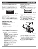
Error code
is displayed (See Figure
157).
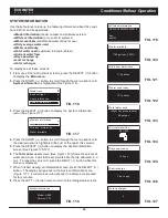
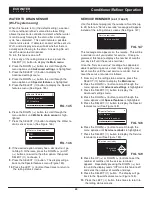
Error detected
Error code: 1
FIG. 157
The troubleshooting chart on the previous page shows
the error codes that could appear, and the possible mal-
functions for these codes.
When an error code appears in the display, pressing
SELECT (
¡
) will display the
Diagnostics
screen (See
Page 41), so a service technician can further isolate the
problem.
REMOVING ERROR CODE
1
. Unplug power supply from electrical outlet.
2
. Correct problem.
3
. Plug power supply back in.
4
. Wait for eight minutes while controller operates valve
through an entire cycle. The error code will return if
the problem was not corrected.
TROUBLESHOOTING -
MANUAL DIAGNOSTICS
1
. Display the
Diagnostics
screen, following the proce-
dure on Page 41.
2
. Press the DOWN (
6
) or UP (
5
) buttons to scroll
through the list. The following items are displayed:
=
Time
(current)
=
Position time
(counts down the time remaining
in the current valve position)
=
Current position
(of the valve: service, fill,
brine, backwash, fast rinse or moving) See
“Manual Advance Recharge Check” on next
page for position verification.
=
Requested position
(of the valve)
=
Motor state
(on or off)
=
Valve position switch
(open or closed)
=
Turbine count
(indicates water flow) See fol-
lowing section for turbine diagnostics.
=
Salt level sensor
(distance reading of sensor)
=
Drain TDS
(total dissolved solids in ppm)
=
Drain temperature
(°C)
=
Tank light switch
(open or closed)
=
RF module
(detected or not)
=
Error code
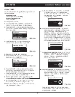
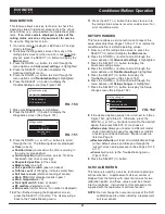
Diagnostics
Turbine count:
0
Salt level sensor:
456
FIG. 158
3
. A steady display of “0” (zero) indicates no water flow
through the meter (i.e. no conditioned water being
used).
4
. Open a nearby conditioned water faucet.
5
. The number in the display should count upward from
0 and reset at 151 for each gallon of flow.
6
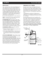
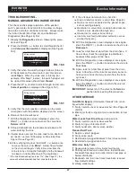
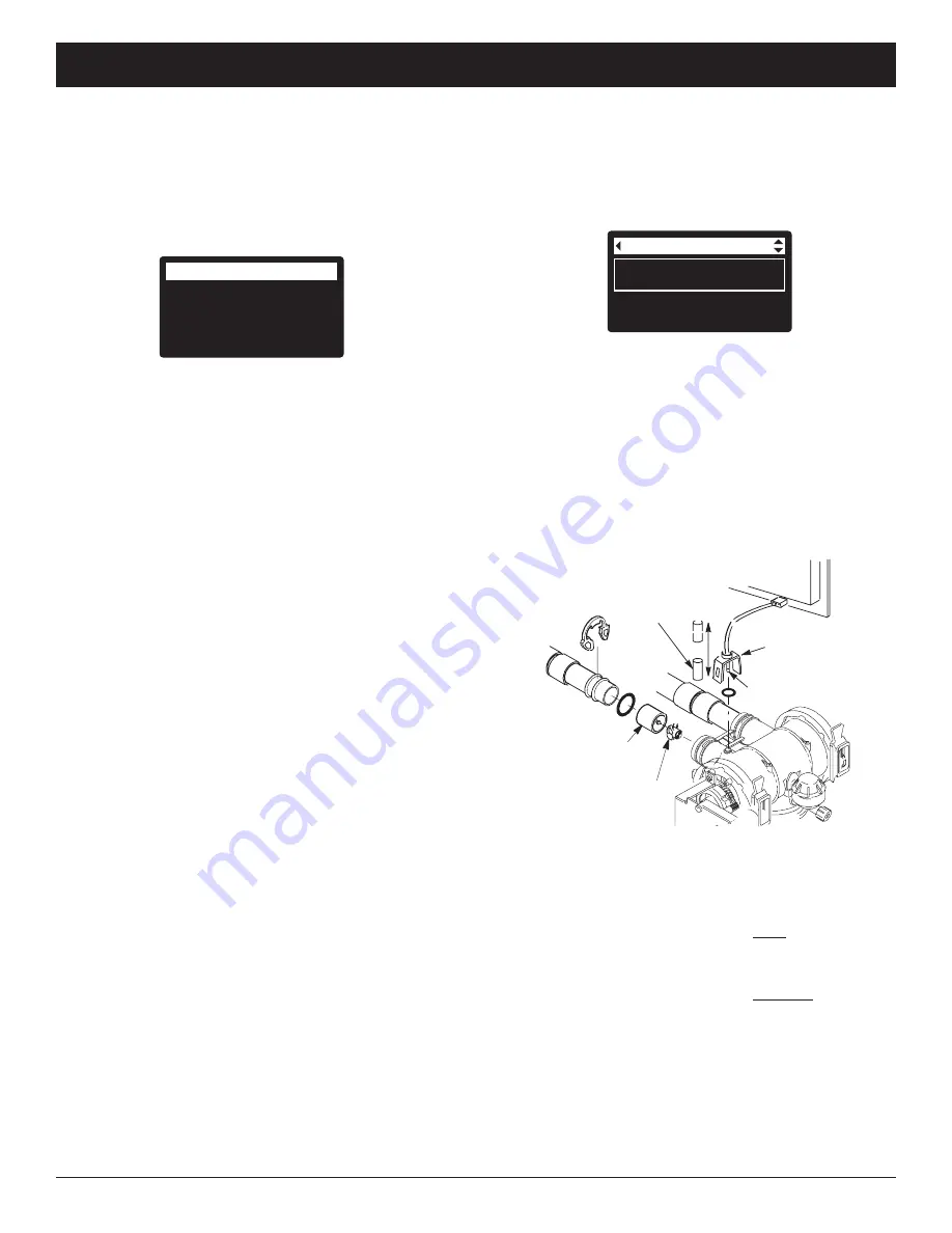
. If the display reading does not change with the
faucet open, pull the wire harness from the valve out-
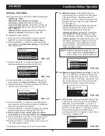
let port (See Figure 159).
turbine
support
turbine
wire harness
BACK OF CONTROLLER
CIRCUIT BOARD
magnet
sensor pickup
FIG. 159
7
. Pass a small magnet back and forth in front of the
sensor.
8a
. If the displayed
Turbine Count
does count upward
with each pass of the magnet, disconnect the outlet
plumbing and check the turbine for binding.
8b
. If the displayed
Turbine Count
does not count
upward with each pass of the magnet, the sensor is
probably faulty.
CHECKING THE TURBINE
1
. Display the
Diagnostics
screen, following the proce-
dure on Page 41.
2
. Press the DOWN (
6
) button to scroll through the list
until
Turbine Count
is displayed (See Figure 158).
ECOWATER
S Y S T E M S
Service Information

