7
ECOWATER
S Y S T E M S
Installation
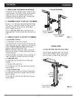
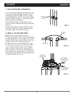
4. INSTALLING THREE-VALVE BYPASS
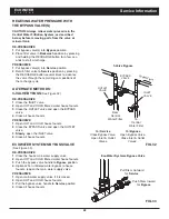
If installing a 3-valve bypass system, plumb as need-
ed using Figure 7 as a guide. When installing sweat
copper, be sure to use lead-free solder and flux,
required by federal and state codes. Use pipe joint
compound on outside pipe threads.
3 VALVE BYPASS
Central Water Filtration
System
INLET
Central Water Filtration
System
OUTLET
FIG. 7
5. ASSEMBLE INLET & OUTLET PLUMBING
Measure, cut, and loosely assemble pipe and fittings
from the main water pipe (or from the bypass valves
installed in Step 4), to the inlet and outlet copper
tubes, installed in Step 2b.
Be sure
incoming water
supply pipe goes to the
valve inlet
side. Trace the water flow direction to be
sure.
6. CONNECT INLET & OUTLET PLUMBING
a. SOLDERED COPPER
(1) Thoroughly clean and flux all joints.
(2) Pull the plastic “C'' clips and remove the inlet and
outlet tubes from the valve. Remove o-rings from the
tubes.
DO NOT solder with tubes in the valve.
Soldering heat will damage the valve.
NOTE:
If installing a ground as shown in Figure 9,
place ground clamps on copper tubes before solder-
ing (See Step 6a).
(3) Make all solder connections. Be sure to keep fit-
tings fully together, and pipes square and straight.
b. THREADED PIPE
(1) Apply pipe joint compound to all outside pipe
threads.
(2) Tighten all threaded joints.
(3) If soldering to the inlet and outlet tubes, observe
Step 6a above.
c. CPVC PLASTIC PIPE
(1) Clean, prime and cement all joints, following the
manufacturer's instructions supplied with the plastic
pipe and fittings.
(2) If soldering to the inlet and outlet tubes, observe
Step 6a above.
CROSS OVER
To Central Water
Filtration System
Main W
ater Pipe
In what direction does the water flow?
Be sure to plan piping so water flow is to the
Central Water Filtration System valve INLET.
Plan a crossover if flow is from left to right.
Treated
Water from
Valve
OUTLET
Untreated
Water to
Valve
INLET
FIG. 8

