6
INSTALLATION - FEED WATER SUPPLY
REJECT WATER DRAIN FITTING
Check and comply with local plumbing codes
as you
plan, then install a cold feed (supply) water fitting. The
fitting must provide a leak tight connection to the RO
1/4" OD tubing, see Figure 6, Page 10. A typical installa-
tion, using standard plumbing fittings is shown in Figure
1. A saddle valve (not available from EcoWater) may be
used where codes permit. Installation instructions are on
Page 22.
NOTE:
Codes in the state of Massachusetts require
installation by a licensed plumber, and do not permit the
use of the drain clamp. For installation, use plumbing
code 248-CMR of the Commonwealth of Massachusetts.
PIPE FITTINGS
(compression shown)
IMPORTANT:
Before starting, close the hot and cold
water shutoff valves (See Figure 1). Use a pan to catch
water when disassembling the pipe.
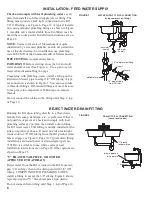
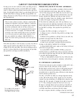
Complying with plumbing codes, install a fitting on the
kitchen cold water pipe to adapt 1/4" OD tubing. A typi-
cal connection is shown in Figure 1. You can use solder
or threaded fittings. If threaded fittings are used, be sure
to use pipe joint compound or Teflon tape on outside
threads.
Do not connect the tubing to the fitting until Step 2, top
of Page 10.
Running the RO drain tubing directly to a floor drain,
laundry tub, sump, standpipe, etc., is preferred. If that is
not possible or practical, check and comply with local
plumbing codes as you plan, then install a drain fitting
for RO reject water. This fitting is usually installed at the
sink p-trap (always above). It must provide a leak-tight
connection to 3/8" OD tubing from the RO product water
faucet airgap, see Figure 6, Page 10. Typical drain fitting
installations are listed below. A drain adapter (part no.
7192230) is available to use where codes permit.
Installation instructions are on Page 22. Other options are
shown on Page 25.
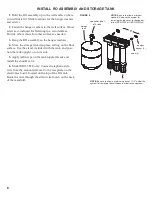
“Y” BRANCH TAIL PIECE, OR OTHER
APPROVED P-TRAP DRAIN
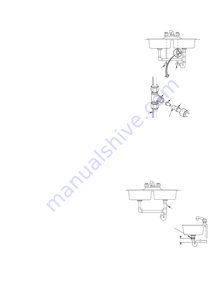
Reject water from the RO is routed to the RO faucet air-
gap (1/4" tubing), then to the drain point with 3/8" OD
tubing. COMPLYING WITH PLUMBING CODES,
install a fitting to accept the 3/8" tubing. Figure 2 shows
typical p-trap and "Y" branch tail piece type drains.
Do not connect drain tubing until Step 1, top of Page 10.
FIGURE 1
FIGURE 2
WATER SUPPLY TYPICAL CONNECTION
(using compression fitting)
hot water
shutoff
cold water
shutoff
cold
water pipe
1/4” compression fitting
insert
ferrule
1/4” green tubing
from RO inlet
DRAIN TYPICAL CONNECTION
(check local codes)
“Y” branch
tailpiece drain
other approved
p-trap drain
3” minimum

