Planning Installation
ECOWATER
S Y S T E
M S
3
6
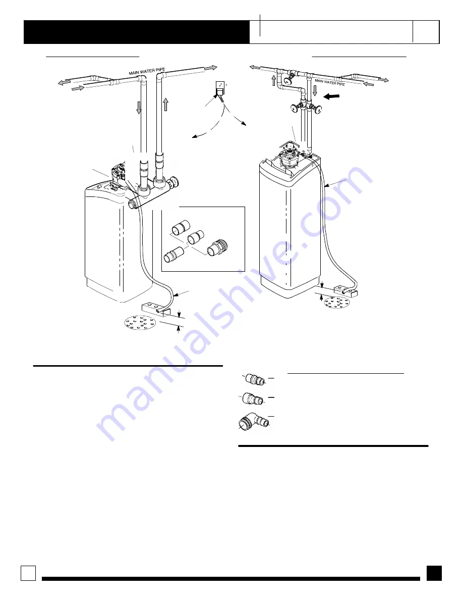
FIGURE 2 -- TYPICAL INSTALLATION DRAWINGS
INLET -- OUTLET OPTIONS
1”copper tube
(2 supplied)
1”x 1”sweat
1”x 3/4”sweat
1”sweat x 1”
or 3/4”pipe
thread
floor drain
floor drain
NOTE: Faceplate and support
not shown for clarity of drawing.
Tie or wire valve drain hose in place,
to keep over floor drain.
valve drain hose
valve drain hose
1--1/2”
airgap
120V, 60Hz
outlet
transformer
(supplied)
to timer
to timer
1--1/2”
airgap
INLET
INLET
OUTLET
OUTLET
3-- valve
bypass system
inlet
valve
outlet
valve
bypass
valve
UNFILTERED
WATER
UNFILTERED
WATER
FILTERED
WATER
OUTSIDE
FAUCETS
OUTSIDE
FAUCETS
INLET -- OUTLET PLUMBING OPTIONS
1.
ALWAYS INSTALL either an EcoWater bypass
valve, #7214383, or a 3 valve bypass system.
2.
Use 1”... or, 3/4”(minimum) pipe and fittings.
3.
Use sweat copper... or, threaded pipe*... or, PVC
plastic pipe.*
*Sweat soldering is required to adapt to the fittings
(1”male) supplied with the filter, or obtain approved
compression adaptors. The following special fittings
are available from EcoWater.
Be sure to comply
with all local plumbing codes.
OPTIONAL INLET/OUTLET FITTINGS
#7104546 PVC Nipple --- Use in place of
included copper inlet and outlet tubes.
#7129211 Adaptor Fitting, 1–1/2”(2) --- Use in
place of included copper inlet and outlet tubes.
#7120259 Elbow --- Extends inlet and/or outlet in
any 90° direction.
OTHER REQUIREMENTS
4.
A drain is needed for regeneration discharge wa-
ter. A floor drain, close to the filter is preferred. A
laundry tub, standpipe, etc., are other options.
CAUTION:
DRAIN WATER EXITS THE HOSE AT
A FAST FLOW RATE, AND AT WATER SYSTEM
PRESSURE. BE SURE THE HOSE IS FASTENED
IN SOME MANNER TO PREVENT “WHIPPING”,
AND SPLASHING TO PREVENT WATER DAMAGE
TO SURROUNDING AREA.
5.
A 120v--60Hz, grounded electrical outlet (contin-
uously “live”is need within 10’of the filter.


