background image

19

ECOWATER

S Y S T E M S

Filter Operation

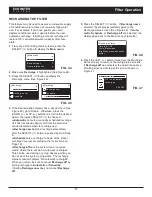
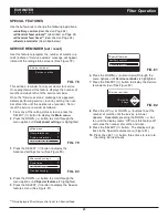
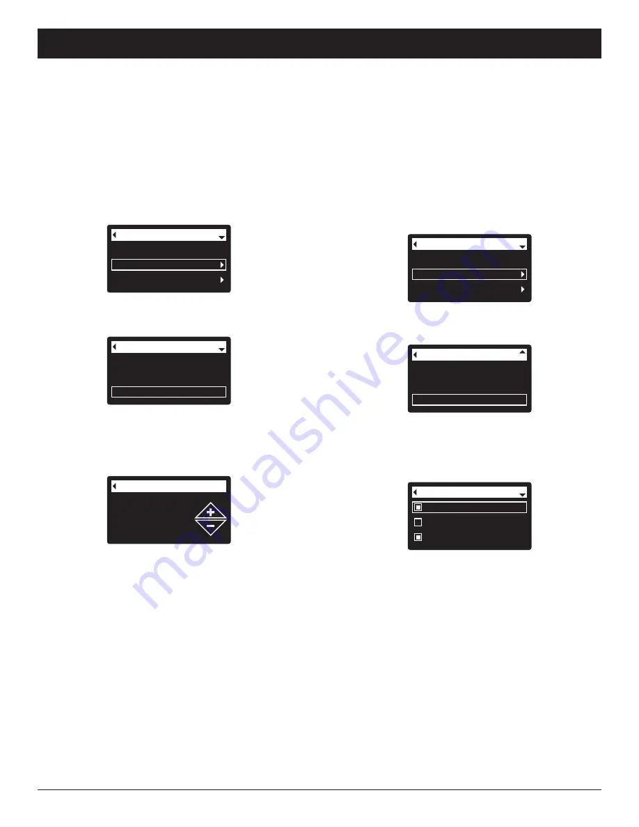
MODIFYING ROLLING SCREENS

During normal filter operation, up to four status screens

are shown in sequence (See “Filter Status Screens” on

Page 14).  When the filter’s electronic control is first

powered up, the default is to show all four.  You can

turn on/off individual screens*:

1

. From any of the rolling status screens, press the

SELECT (

¡

) button to display the 

Main menu

.

2

. Press the DOWN (

6

) button to scroll through the

menu options until 

Basic settings

is highlighted

(See Figure 54).

3

. Press the SELECT (

¡

) button to display the Basic

settings menu (See Figure 55).

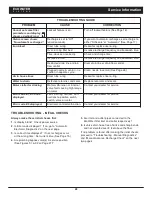
Recharge
Basic settings
User preferences

Main menu

FIG. 54

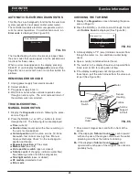
Max. days between rech...
Recharge time
Rolling screens

Basic settings

FIG. 55

4

. Press the DOWN (

6

) button to scroll through the

menu options until 

Rolling screens

is highlighted.

5

. Press the SELECT (

¡

) button to display the Rolling

screens menu (See Figure 56).

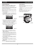
Water use
Flow rate
Recharge status

Rolling screens

FIG. 56

6

. Press the DOWN (

6

) or UP (

5

) buttons to scroll

through the list.  Items with a black square next to

them will be displayed during normal operation.

7

. To un-select a screen, make sure its name is high-

lighted in a box.  Then press the SELECT (

¡

) button.

The black square will disappear.  Pressing SELECT

(

¡

) again makes the black square reappear and re-

selects the highlighted item.  At least one screen

must be selected/highlighted.

8

. When selections are complete, exit this menu by

pressing the LEFT (

3

) button.  The display will go

back to the Basic settings menu (Figure 55).

9

. Press the LEFT (

3

) button twice to return to the

rolling status screens.

   *

This does not include service reminders, errors, alerts or

Recharge status screens.

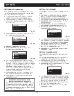
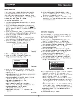
SETTING RECHARGE TIME

When the filter’s electronic control is first powered up,

the default time for starting an automatic recharge is

12:00 a.m.  This is a good time in most households

because water is not being used.  To change this time:

1

. From any of the rolling status screens, press the

SELECT (

¡

) button to display the 

Main menu

.

2

. Press the DOWN (

6

) button to scroll through the

menu options until 

Basic settings

is highlighted

(See Figure 51).

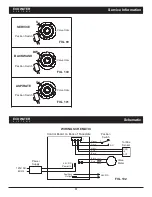
Current time
Max. days between rech...
Recharge time

Basic settings

FIG. 52

3

. Press the SELECT (

¡

) button to display the Basic

settings menu (See Figure 52).

Recharge time

12:00 AM

FIG. 53

Recharge
Basic settings
User preferences

Main menu

FIG. 51

4

. Press the DOWN (

6

) button to scroll through the

menu options until 

Recharge time

is highlighted.

5

. Press the SELECT (

¡

) button to display the

Recharge time screen (See Figure 53).

6

. Press the UP (

5

) or DOWN (

6

) buttons to change

the recharge time in 1 hour increments.  Hold the

button down to rapidly advance.  Be sure that AM or

PM is correct (unless filter is set for a 24-hour clock).

7

. Press the SELECT (

¡

) button.  The display will go

back to the Basic settings menu (Figure 52).

8

. Press the LEFT (

3

) button twice to return to the

rolling status screens.

Summary of Contents for ETF2300AIV10

Page 1: ...x 64420 St Paul MN 55164 0420 www ecowater com Designed Engineered Assembled in the U S A ETF2300AIV10 and ETF2300AIV12 are tested and certified by the Water Quality Association against NSF ANSI Standard 372 for low lead content ETF2300EIV10 and ETF2300EIV12 are tested and certified without media by the Water Quality Association against CSA B483 1 NSF ANSI 61 and NSF ANSI Standard 372 for low lead...

Page 2: ...ages incluant tous brouillages qui peut nuire au bon fonctionnement du dispositif European Directive 2002 96 EC requires all electrical and electronic equipment to be dis posed of according to Waste Electrical and Electronic Equipment WEEE requirements This directive or similar laws are in place nationally and can vary from region to region Please refer to your state and local laws for proper disp...

Page 3: ...nd organically bound iron Consult media specifications for contaminant limitations Well pump must be able to provide the minimum flow for 30 minutes Consult manufacturer for applications with bacterial or organically bound iron Install a backwash flow control that is appropriately sized for the media used A FRONT VIEW SIDE VIEW TOP VIEW 14 1 4 13 5 8 IN 3 3 4 OUT IN OUT B ECOWATER S Y S T E M S Sp...

Page 4: ...e filter must be less than 120 F Keep outside faucets on unfiltered water to con serve filtering capacity Do not install the filter in a place where it could freeze Damage caused by freezing is not cov ered by the warranty Put the filter in a place water damage is least likely to occur if a leak develops The manufacturer will not repair or pay for water damage A 120V 60 Hz electrical outlet to plu...

Page 5: ...a 8 Flush the tank opening with water to clean media particles from the top of the tank Uncover the bot tom distributor stand tube 9 Fill the tank with water up to the top of the tank IMPORTANT Be sure to fill with water This will elim inate air space wet the media and pre vent excessive air head pressure when filter is pressurized 10 Install the o ring seals and top distributor exactly as shown i...

Page 6: ...G 7 FIG 6 INSTALLATION USING 3 VALVE BYPASS MAIN WATER PIPE MAIN WATER PIPE INSTALLATION USING ECOWATER BYPASS VALVE CROSS OVER Use if water supply flows from the left Include single or 3 valve bypass Filtered Water OUT Unfiltered Water IN FILTERED WATER TO FILTER INLET UNFILTERED WATER FROM FILTER OUTLET BYPASS Valve OUTLET Valve INLET Valve O Ring Seal 2 Valve INLET For filtered water SERVICE Op...

Page 7: ...ic adaptor to make sure they are held securely in place 3 COMPLETE PLUMBING TO AND FROM THE FILTER Using the Typical Installation Illustrations on page 6 as a guide observe all of the following cautions while you connect inlet and outlet plumbing Be sure incoming unfiltered water is directed to the valve INLET port Be sure to install bypass valve s If making a soldered copper installation do all s...

Page 8: ...ting f Allow the unit to complete the 15 minute backwash cycle and automatically advance to the aspirate A position Allow it to remain there as it aspirates air into the mineral tank After 75 minutes the filter will then automatically return to service Start up is complete 4 COLD WATER PIPE GROUNDING The house cold water pipe metal only is often used as a ground for the house electrical system The...

Page 9: ...or check valve See Figure 15 4 Insert the free end of the tubing into the hydrogen peroxide container 5 Start a recharge From the rolling status screens press the SELECT button to display the Main menu Make sure Recharge is highlighted then press SELECT Press DOWN 6 to scroll to Recharge now then press SELECT twice You should hear the valve motor run as the filter begins recharging The filter will...

Page 10: ...to Step 4 English Español Français Language ECOWATER S Y S T E M S Setup Procedure Push wireless router button Wireless setup Cancel FIG 19 Connected Key abc123 Wireless setup Continue FIG 20 Pushbutton WPS Option 4 Use the SELECT button to choose Pushbutton WPS The filter display will change to show Push wireless router button 5 Press the WPS or Push to Connect button on your router and wait for ...

Page 11: ...ur router is not connected to the internet Verify that the router s internet connection works with your laptop or other device 15 On your laptop tablet or phone go back to the view of networks in range and make sure that your device is connected back to your local network Finish Setting up the Filter 16 Once you have connected the Wi Fi system and written down your key code press the SELECT button...

Page 12: ... and display all systems again by clicking the Home tab See the following page for instructions on how to share a system NOTE A dealer registering filters must log in as a dealer not as a customer 25 In your internet browser type in this URL http wifi ecowater com 26 If you are a dealer and have an account log in to your account and go to the next step If you are a customer go to Page 13 for instr...

Page 13: ... click the Connect button to advance to the System Settings screen 10 Fill in the System Settings screen and click the Save Settings button 11 Fill in the Communication Preferences screen and click the Save and Continue button 12 The screen should change to show the Home page for your system including the filter dashboard Click the Log Out tab when you are done VISITING YOUR CUSTOMER ACCOUNT Any t...

Page 14: ... recharges showing valve position and time remaining Recharge status Off no automatic recharges instead of rolling screens indicates that automatic recharges have been turned off See Page 17 Current time setting screen instead of status screens indicates time has been lost perhaps after a long power loss Set the time See next page Service reminder See Page 23 Error detected Contact your dealer for...

Page 15: ...ess the LEFT 3 button twice to return to the rolling status screens NOTE On Wi Fi connected systems the current time will be updated and maintained automatically via Wi Fi Current time 12 34 PM FIG 38 During normal operation status screens rolling press the filter s SELECT button to display the Main menu See Figure 35 This menu and its subsidiary screens are used to control these operations Rechar...

Page 16: ... changes 8 Press the RIGHT 4 button A flashing padlock icon will appear as shown in Figure 40 9 Press the SELECT button 10 Press the LEFT 3 button three times to return to the rolling status screens ECOWATER S Y S T E M S Filter Operation LOCKOUT FEATURE A lockout feature is available to prevent user modifica tion of parameters that affect filter performance The unit is shipped from the factory wi...

Page 17: ...harge will restore 100 conditioned water capacity after com plete 1 From any of the rolling status screens press the SELECT button to display the Main menu 4 If the desired option already has a dot next to it See Figure 45 go to Step 5 Otherwise press the DOWN 6 or UP 5 buttons to scroll to the desired option then press SELECT to choose it Automatic cancels a manually scheduled recharge if it has ...

Page 18: ...ghted 5 Press the SELECT button to display the Max days between recharges screen See Figure 50 6 Press the UP 5 or DOWN 6 buttons to change the number of days between automatic recharges The feature can be set from 1 to 99 days When the filter s electronic control is first powered up a wizard screen prompts you to set the number of days between automatic recharges See Page 11 To change it 1 From a...

Page 19: ...e screen must be selected highlighted 8 When selections are complete exit this menu by pressing the LEFT 3 button The display will go back to the Basic settings menu Figure 55 9 Press the LEFT 3 button twice to return to the rolling status screens This does not include service reminders errors alerts or Recharge status screens SETTING RECHARGE TIME When the filter s electronic control is first pow...

Page 20: ...SELECT button The display will go back to the User preferences menu 8 Press the LEFT 3 button twice to return to the rolling status screens ECOWATER S Y S T E M S Filter Operation SETTING THE LANGUAGE When the filter s electronic control is first powered up a wizard screen prompts you to set the language See Page 10 To change the language 1 From any of the rolling status screens press the SELECT b...

Page 21: ...utton to scroll through the menu options until the desired option is highlighted See list at the top of this column 5 Press the SELECT button to display the desired information screen See Figures 64 72 6 The Total water used screen See Figure 68 shows the volume of water used since it was last reset it works like the trip odometer in a car To reset the value to 0 press the RIGHT 4 button while thi...

Page 22: ...ress the LEFT 3 button three times to return to the rolling status screens Cycle times Special features Troubleshooting Advanced settings FIG 74 4 Make sure Cycle times is highlighted 5 Press the SELECT button to display the Cycle times menu See Figure 75 User preferences System information Advanced settings Main menu FIG 73 3 Press the SELECT button to display the Advanced settings menu See Figur...

Page 23: ...ns to set the number of months until the service reminder appears Repeatedly pressing the DOWN 6 but ton until the display reads Off turns this feature off and zeros the number of months and days 9 Press the SELECT button The display will go back to the Special features menu Figure 81 10 Press the LEFT 3 button three times to return to the rolling status screens 6 Press the DOWN 6 button to scroll...

Page 24: ...feed volume and timer must be set as detailed at right Water use Turns 24V DC on when the filter s tur bine indicates water flow Could drive an air pump for iron or sulfur oxidation Fast Rinse Turns 24V DC on during the fast rinse portion of the regeneration cycle 9 Press the SELECT button The display will go back to the Special features menu Figure 83 10 Press the LEFT 3 button three times to ret...

Page 25: ...ighted 7 Press the SELECT button to display the Setup changes menu See Figure 89 Diagnostics Setup changes Troubleshooting FIG 87 7 Make sure Diagnostics is highlighted 8 Press the SELECT button to display the Diagnostics screen See Figure 88 Diagnostics Time 3 45 PM Position time 0 00 FIG 88 9 Press the DOWN 6 or UP 5 buttons to scroll through the list The following items are displayed Time curre...

Page 26: ...r Be sure to clean both the top and bottom of the nozzle venturi disc If needed use a small brush to remove iron or dirt Do not scratch misshape etc surfaces of the nozzle venturi Gently replace all parts in the correct order Lubricate the o ring seal with silicone grease and locate in place Install and tighten the cap by hand while sup porting the housing Overtightening may break the cap or housi...

Page 27: ...PASS valve 4 Close all house faucets PRESSURIZE 1 Open HOT and COLD house faucets 2 Close the BYPASS valve and open the OUTLET valve 3 Slowly open the INLET valve 4 Close all house faucets ECOWATER SYSTEMS BYPASS VALVE See Figure 92 DE PRESSURIZE 1 Close the house main water supply valve 2 Open HOT and COLD conditioned water house faucets 3 Push the bypass valve handle to Bypass position 4 Optiona...

Page 28: ...als Replace rotor disc and seals Motor stalled or clicking Motor malfunction or internal valve fault causing high torque on motor Contact your dealer for service Error code E1 E3 or E4 displayed Fault in wiring harness con nections to position switch switch valve or motor Contact your dealer for service Error code E5 displayed Electronic control malfunction Contact your dealer for service TROUBLES...

Page 29: ...n of the valve service fill brine backwash fast rinse or moving See Manual Advance Recharge Check on the next page for position verification Requested position of the valve Motor state on or off Valve position switch open or closed Turbine count if changing indicates water flow See following section for turbine diagnostics Tank light switch open or closed RF module detected or not Error code Diagn...

Page 30: ...ed top distributor back wash flow plug or drain hose 8 With the Diagnostics screen displayed once again press the RIGHT 4 button to advance the valve to Fast rinse Aspirate 9 With the Diagnostics screen displayed once again press the RIGHT 4 button to return the valve to the Service position IMPORTANT Always return the valve to the Service position before exiting this procedure Diagnostics Valve p...

Page 31: ... A ASPIRATE Position Switch Valve Cam FIG 101 Position Switch ECOWATER S Y S T E M S Schematic WIRING SCHEMATIC 1 Orange Green Red Black Control Board on Back of Faceplate Valve Motor Position Switch NO C Power Supply 120V AC 60 Hz 24V DC Power In Auxiliary Output 24V DC FIG 102 White Red Black Turbine Sensor GND 5 OUT ...

Page 32: ...32 ECOWATER S Y S T E M S Notes ...

Page 33: ...7353242 Shroud ETF2300AIV12 ETF2300EIV12 7331177 Tank Neck Clamp Kit includes 2 ea of Key Nos 11 12 11 á Clamp Section 2 req 12 á Retainer Clamp 2 req 7112963 Distributor O Ring Kit includes Key Nos 13 15 13 á O Ring 2 7 8 x 3 1 4 14 á O Ring 13 16 x 1 1 16 15 á O Ring 2 3 4 x 3 16 7335757 Top Distributor 17 7105047 Repl Bottom Distributor 18 7092202 Repl Mineral Tank 10 x 47 ETF2300AIV10 ETF2300E...

Page 34: ...rts 50 94 93 92 91 90 79 80 78 76 77 Wear Strip Seal Cross section View 63 66 67 62 61 60 59 58 57 56 55 54 70 72 71 72 74 95 51 52 53 64 68 69 65 83 Assembled View Flow Plug Assembly 70 81 82 89 88 87 86 85 84 VALVE EXPLODED VIEW 73 75 ...

Page 35: ...2 req 7336410 O Ring 1 1 16 x 1 5 16 pack of 20 Key No Part No Description 73 7343873 Inlet Check Valve w O Ring 7331703 Turbine Support Assembly including 2 O Rings See Key No 72 1 ea of Key Nos 74 75 74 á Turbine Support Shaft 75 á Turbine 76 7081201 Retainer Nozzle Venturi 77 7171145 Valve Body 78 7170319 O Ring 1 4 x 3 8 2 req 79 7336208 Air Inlet Screen 80 7336193 Aspirator Check Valve 81 712...

Page 36: ... sells an EXTENDED PARTS ONLY WARRANTY for the ELECTRONICS portion of your product This warranty is called the Perfect Ten and extends the three year warranty on the electronic FACE PLATE WIRING HARNESS DRIVE MOTOR POWER SUPPLY POWER CORD SENSOR HOUSING and MICRO SWITCH ES to a total of TEN YEARS from the date of original installation Your local dealer will provide details regarding this warranty ...

Reviews: