5
ECOWATER
S Y S T E M S
Media Loading (Models ETF2300EIV10 & ETF2300EIV12)
MEDIA LOADING
Models ETF2300EIV10 & ETF2300EIV12
, as manu-
factured, have no media other than quartz gravel at
the bottom of the tank (See table on Page 3 for
amounts). Before plumbing these units, load media:
1
. Move the filter into installation location and set it on
a flat, level surface. If a twin installation, keep
tanks separated for ease of service.
2
. Take off the unit’s top cover and unplug the wiring
connections between the valve and the control
board (PWA).
3
. Remove retainer clips and clamp sections from the
tank neck and carefully lift the valve off the tank.
4
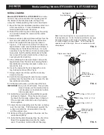
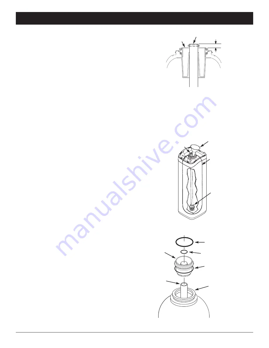
. Check the height of the riser pipe as shown in
Figure 3. If riser pipe is more than 1/2” above the
top distributor, make sure that bottom distributor is
below gravel at the bottom of the tank. It may be
necessary to lay the filter on its side to move gravel
to one side, hold the bottom distributor at the bot-
tom center of the tank and stand the unit back up.
Level gravel after checking.
5
. After confirming the riser pipe height, remove the
top distributor from the tank neck, leaving the bot-
tom distributor (including riser pipe) in place, cen-
tered in the tank.
6
. Cover the top end of the riser pipe with a clean
rag, to keep media out (See Fig. 4).
7
. Using a larger neck funnel, add the necessary
amount of media.
8
. Flush the tank opening with water to clean media
particles from the top of the tank. Uncover the bot-
tom distributor stand tube.
9
. Fill the tank with water, up to the top of the tank.
IMPORTANT:
Be sure to fill with water. This will elim-
inate air space, wet the media and pre-
vent excessive air-head pressure when
filter is pressurized.
10
. Install the o-ring seals and top distributor exactly
as shown in Figure 5. Place the small o-ring at
the top of the riser pipe, where shown in Figure 3.
If the o-rings need lubrication, use a high quality
silicone grease.
11
. Lower the valve assembly onto the tank, centering
over the riser tube. Push downward, against the
o-ring, and install the clamp sections, securing
with the retainer clips.
12
. Reconnect the wiring between the valve and the
control board (PWA).
13
. Verify that the drain flow plug (See Key No. 59 on
Page 35) is appropriately sized for the media
used. If necessary, install a different flow plug.
FIG. 5
Top
Distributor
Bottom
Distributor
Riser Pipe
O-Ring, 2-7/8” x 3-1/4”
Make sure o-ring
sealing surfaces
are clean
O-Ring, 13/16” x 1-1/16”
O-Ring, 2-3/4” x 3”
Top Edge of
Top Distributor
Riser Pipe
0” to 1/2”
Note:
Resin tank height can vary somewhat within manu-
facturing tolerance. So that the bottom distributor riser pipe
has proper clearance with inside valve porting, check for
the correct length, as shown above. Cut the riser pipe if
needed to adjust the length. Be sure to remove burrs and
sharp edges.
FIG. 3
FIG. 4
Funnel
Plug or cover top of
riser pipe
Tank
Make sure
bottom distributor
is centered


