ECOWATER
S Y S T E M S
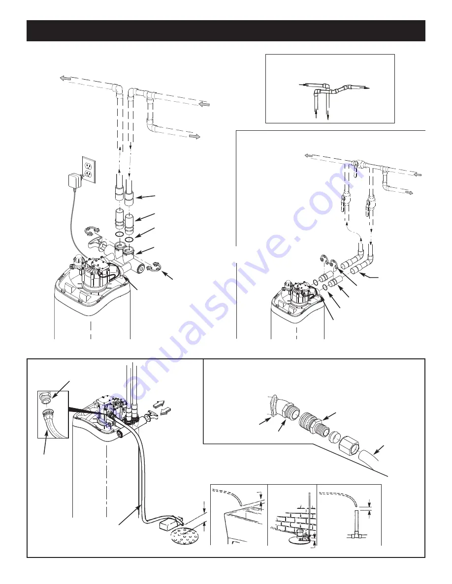
Typical Installation Illustrations
6
FIG. 8
Drain
Fitting
Valve
Drain
Hose
Valve
Drain
Hose
1-1/2”
Air Gap
1-1/2”
Air Gap
1-1/2””
Air Gap
1-1/2” Air Gap
LAUNDRY
TUB
SUMP
STAND
PIPE
FLOOR
DRAIN
To standpipe, sump, laundry
tub or other suitable drain.
5/8” I.D.
(minimum)
copper tube
Push
in
for
Bypass
Clip
Drain Fitting
CONNECTING A RIGID VALVE DRAIN TUBE
To adapt a copper tube to the filter, buy a compression fitting (garden hose thread to
5/8” I.D. minimum tube and necessary tubing from your local hardware store.
Adaptor, garden hose
thread to compression
Pull
out
for
filtered water
“
Service”
FIG. 7
FIG. 6
INSTALLATION USING 3-VALVE BYPASS
MAIN WATER PIP
E
MAIN WATER PIP
E
INSTALLATION USING ECOWATER BYPASS VALVE
CROSS-OVER
Use if water supply flows from the left.
Include single or 3-valve bypass.
Filtered
Water
OUT
Unfiltered
Water
IN
FILTERED
WATER
TO FILTER
INLET
UNFILTERED
WATER
FROM FILTER
OUTLET
BYPASS
Valve
OUTLET
Valve
INLET
Valve
O-Ring Seal (2)*
Valve
INLET
For filtered water SERVICE:
-Open the inlet and outlet
valves
For unfiltered BYPASS:
-Close the inlet and outlet
valves
-Open the bypass valve
Unfiltered Water
to Outside Faucets
* Included with filter - Pipe and
fittings supplied by installer.
1” Copper Tube (2)*
#7214383
Bypass
Valve
Clip (2)*
O-Ring Seal (2)*
1” Sweat Adaptor (2)
not included
Valve
INLET
1” Sweat
Adaptor (2)
not included
1” Copper Tube (2)*
120V,
60 Hz
Outlet
Clip (2)*
Tie or
wire
tubing
in place


