9
ECOWATER
S Y S T E M S
Description of Operation
Service water enters the filter and passes through air
captured at the top of the mineral tank. Dissolved iron
is oxidized and then removed by the media in the
tank. When the system recharges, it first backwash-
es the contaminants to the drain, then empties the
tank of water, replacing it with air drawn through the
aspirator. When the system returns to "service", the
water pressure will compress the air in the mineral
tank and leave an 8-14" head of air on the top of the
tank.
Care is taken at the factory to keep your water filter
clean and sanitary. Materials used to make the filter
will not infect or contaminate your water supply, and
will not cause bacteria to form or grow. However,
during shipping, storage, installing and operating,
bacteria could get into the filter or media. For this
reason, sanitizing as follows is suggested* when
installing.
1
. Obtain pharmaceutical grade 12% hydrogen perox-
ide solution. One quart (0.95 L) is required for a
10" filter, 2 quarts (1.9 L) for a 12" filter.
2
. Remove air inlet screen from check valve on the
valve’s nozzle & venturi assembly (See Figure 14).
3
. Connect a length of 3/8 I.D. tubing to the barb on
the aspirator check valve (See Figure 15).
4
. Insert the free end of the tubing into the hydrogen
peroxide container.
5
.
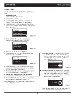
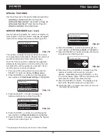
Start a recharge:
From the rolling status screens,
press the SELECT (
¡
) button to display the
Main
menu
. Make sure
Recharge
is highlighted, then
press SELECT (
¡
). Press DOWN (
6
) to scroll to
Recharge now
, then press SELECT (
¡
) twice.
You should hear the valve motor run as the filter
begins recharging. The filter will backwash for 15-
17 minutes, then advance automatically to the
“aspirate” position. It will draw the hydrogen perox-
ide into the filter and pass it through the zeolite
media, cleaning and sanitizing the media.
6
. Allow the filter to draw air for the remainder of the
time in the “aspirate” cycle after the hydrogen per-
oxide has been drawn into the filter.
7
. The filter will return to “service” automatically when
the “aspirate” cycle is complete.
8
. Remove tubing and reinstall the aspirator inlet
screen onto the barbed fitting on aspirator check
valve.
9
. Cleaning/sanitizing process is complete.
*
NOTE:
Sanitizing is recommended by the Water Quality
Association for disinfecting. On some water sup-
plies, they suggest periodic sanitizing.
FIG. 14
FIG. 15
Valve nozzle &
venturi assembly
Valve nozzle &
venturi assembly
Place other end of tube in
hydrogen peroxide solution
Check valve
3/8” barb
Remove air
inlet screen
Check valve
3/8” barb
Connect 3/8” I.D.
tubing to barb
ECOWATER
S Y S T E M S
Sanitizing Procedure


