17
4.3 Wi-Fi Gateway Introduction
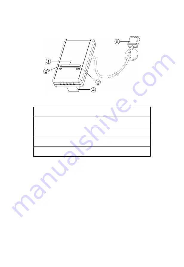
See Figure 10 to help you identify elements of the gateway.
Figure 10: Gateway Introduction
1 Wi-Fi Configure/Reset Button
2. RF Status Indicator Light (Blue)
3. Wi-Fi Status Indicator Light (Red)
4. USB Connector for system power supply
5. Temperature, humidity and barometric 3-in-1 sensor
Table 4: gateway parts identification
Before configuring the gateway with your mobile application, please read
the description of the LED indicators (2 and 3), and button function for
better understanding.
4.3.1 LED Indicators
RF
(Blue): Indicates RF data receiving status
Flash
(each): indicates one packet of RF data from a sensor was
received.
Off
(steady): indicates no RF data received.
Wi-Fi
(Red): Indicates Wi-Fi connection status
Summary of Contents for GW1001
Page 26: ...26 Figure 14 Weather Services uploading setting screen ...
Page 30: ...30 Graph display List display ...
Page 42: ...42 You may view your weather station data by pressing your device on this screen ...
Page 46: ...46 https itunes apple com us app pws weather station monitor id713705929 ...


