background image

ww.ecoxotic.com

P

0-10V Ramp Timer

     Instructions 

Installation Instructions 

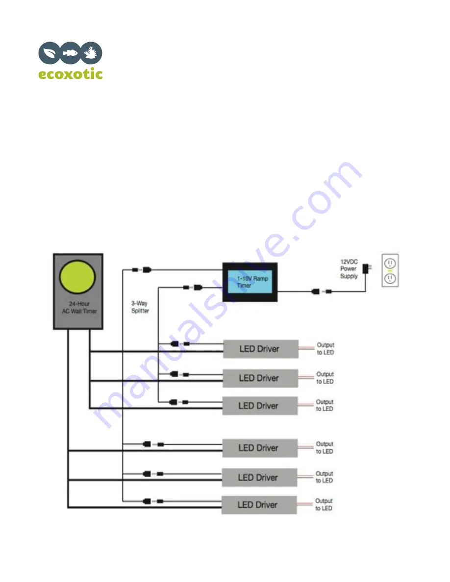
The below diagram is a basic guideline for connecting up to 6 dimmable LED drivers to the 0-10V Ramp Timer.  If your
LED lighting system consists of two color spectrums (white and blue), we recommend connecting the dimmable LED
drivers for the blue spectrum lights to Channel 1, the dimmable driver for the white spectrum lights to Channel 2.  

If using less than 6 units, we recommend not exceeding 3 drivers per channel. The drivers/lights can be installed on either channel.
It is not necessary to use both channels on the 0-10V Ramp Timer.

Please follow the steps on the following pages for detailed installation and programming.

Figure 1

GFCI Outlet

Page 3 of 10

Summary of Contents for 0-10 Ramp Timer

Page 1: ...ion that you should read for future refer ence Remember you can always find more information on our website discard the appliance or the timer controller and examine it for the presence of water timer 0 Celsius or 32 Fahrenheit If an extension cord is necessary a cord with a rating of at least 15 Amperes should be used A cord rated for less Amperes or watts that the fixtures may overheat Care shou...

Page 2: ...river either by a standard wall timer or power circuit timer The Ramp Timer can be kept plugged in at all times for 24 hour ramp dimming and intensity control We recommend not exceeding 6 dimmable LED drivers to be connected to the 0 10V Ramp Timer 3 LED drivers per channel Warning This product must be installed by a licensed electrician Before beginning any work on the electrical installation be ...

Page 3: ...mmend connecting the dimmable LED drivers for the blue spectrum lights to Channel 1 the dimmable driver for the white spectrum lights to Channel 2 If using less than 6 units we recommend not exceeding 3 drivers per channel The drivers lights can be installed on either channel It is not necessary to use both channels on the 0 10V Ramp Timer Please follow the steps on the following pages for detaile...

Page 4: ...n away from direct contact from moisture and or water 5 Connect the 12VDC transformer to the female DC plug on the Ramp Timer Plug 12VDC power supply into a GFCI approved outlet where power will be kept on 24 hours per day 6 Connect the male DC plug of Channel 1 or Channel 2 to either a 3 way splitter or directly to Female DC dimming plug If using two different color spectrum Cannon LED pendants w...

Page 5: ...ver Dimming Cable Channel 1 0 10V Controller 12VDC Transformer To GFCI No timer Channel 2 To AC Timer or GFCI To AC Timer or GFCI Typical wiring diagram for wall mount LED drivers These include Inventronics dimmable LED drives and Meanwell HLG and ELN dimmable LED drivers Typical wiring diagram for circular mounted LED drivers These include Meanwell HBG dimmable LED drivers Page 5 of 10 ...

Page 6: ...mming Instructions Please read the following guides before following the detailed programming instructions located on the following page Programming Feature Guide The 0 10V Ramp Timer features two independent lighting channels with the following Program on off times for each channel dimming down to 10 Adjustable intensity 10 100 for each channel Adjustable ramp up sunrise dim down sunset 0 30 minu...

Page 7: ...g your wireless remote point the remote directly at the IR sensor located on the 0 10V Ramp Timer It is important to have a direct line of sight between the remote and the controller Digital LCD Display Guide 0 10V Ramp Timer Instructions Page 7 of 10 6 ...

Page 8: ... spectrum lights for dawn dusk actinic moon lighting Channel 2 Line 2 should be connected to your white spectrum lights for daylight SUNRISE SUNSET FADE The duration of the ramp up and dim down 0 30 minutes To reset the memory settings to the factory default press DEFAULT for 5 seconds see pg 5 Default This will reset the controller memory for all four memory settings Determines what time your lig...

Page 9: ...s Press TIMER M1 TIMER M2 TIMER M3 or TIMER M4 SL 1 SL 2 SL 3 or SL 4 will display on the screen The intensity can be used as a reference when programming your minimum and maximum settings 10 to 100 to 10 min The 0 10V Ramp Timer features five total memory locations 0 10V Ramp Timer Instructions Page 9 of 10 ...

Page 10: ...istration of such Product If the returned Product is not defective or is returned after the Warranty Period Ecoxotic shall have no obligation to repair or replace the Product EXCEPT AS EXPRESSLY PROVIDED ABOVE OR AS REQUIRED BY LAW ECOXOTIC PRODUCTS ARE PROVIDED AS IS WITHOUT WARRANTY OF ANY KIND THE WARRANTY AND REMEDIES SET FORTH ABOVE ARE EXCLUSIVE AND IN LIEU OF ALL OTHERS WHETHER ORAL OR WRIT...

Reviews: