background image

Manufactured by: 

ECR International Inc.   

2201 Dwyer Avenue, Utica, NY 13501 

 Tel. 800 325 5479  

www.ecrinternational.com  

PN 240012875 REV. D [03/15/2022]

APPLICATION GUIDE

FOR USE WITH

FLOOR STANDING

HEATING ONLY - 75F, 100F, 125F, 165F

&

COMBI - 115F, 150F, 205F

This manual has been prepared for use with the appropriate Installation, Operation and 

Maintenance Manual.

Summary of Contents for 100F

Page 1: ...el 800 325 5479 www ecrinternational com PN 240012875 REV D 03 15 2022 APPLICATION GUIDE FOR USE WITH FLOOR STANDING HEATING ONLY 75F 100F 125F 165F COMBI 115F 150F 205F This manual has been prepared for use with the appropriate Installation Operation and Maintenance Manual ...

Page 2: ...ank Tank T Stat Wiring Dia 19 115F 150F 205F with zone circulators PIPING Diagram 20 115F 150F 205F with zone Circulators Wiring Diagram 21 115F 150F 205F with Zone Valves PIPING Diagram 22 115F 150F 205F with Zone Valves Wiring Diagram 23 EXTERNAL buffer TANK PIPING Diagram 24 EXTERNAL buffer TANK Wiring Diagram 26 Optional Equipment 29 CHART 1 1k Ω OUTDOOR AIR SENSOR DATA 29 CHART 2 10k Ω INDIRE...

Page 3: ...ead this manual and understand all requirements before beginning installation 3 Installation shall conform to requirements of authority having jurisdiction or in absence of such requirements United States National Fuel Gas Code ANSI Z223 1 NFPA 54 National Electrical Code NFPA 70 Canada Natural Gas and Propane Installation Code CAN CSA B149 1 Canadian Electrical Code Part I Safety Standard for Ele...

Page 4: ...ndensate Drain Connection 1 2 NPT C Gas Shutoff Connection 3 4 NPT D Optional Indirect DHW Connection may exit right or left 3 4 sweat 22 2 mm NA E Heating Return Connection 11 4 sweat 31 8 mm 11 2 sweat 38 1 mm 75F 100F 125F HEATING ONLY WITH OPTIONAL INDIRECT DHW CONNECTION 75F 100F 125F HEATING ONLY WITHOUT OPTIONAL INDIRECT DHW CONNECTION 165F HEATING ONLY E E E A A A D C C C B B B ...

Page 5: ... A Heating Supply Connection 11 4 sweat 31 75 mm 11 2 sweat 38 1 mm B Domestic Hot Water Outlet 1 2 sweat 12 7 mm 3 4 sweat 22 2 mm C Condensate Drain Connection 1 2 NPT D Gas Shutoff Connection 3 4 NPT E Domestic Cold Water Inlet 1 2 sweat 12 7 mm 3 4 sweat 22 2 mm F Heating Return Connection 11 4 sweat 31 8 mm 11 2 sweat 38 1 mm E F A D C B ...

Page 6: ...e CAN CSA B149 1 Manufacturer Requirements Recommendations Manufacturer requires all domestic hot water DHW installations use an anti scald valve Local codes may require additional equipment expansion tank relief valves etc Select and size equipment to suit installation and meet code requirements Use a water filter on potable incoming water supply line Manufacturer recommends use of a magnetic dir...

Page 7: ... boiler pump manifold shall be cut for use as shown on page 24 Increase pipe size to match Buffer tank connections as shown Locate tank as close to boiler as possible The Labor Saver Piping Manifold which is supplied with each boiler is shown with most of the following piping diagrams Use of Indirect Water Heater DHW Heating Only Boiler Note Sensors supplied with this boiler are proprietary to the...

Page 8: ...er Tank and optional use of a H2O Buffer Tank Reference the zone control manufacturer instruction manual for control operation and priority setting of DHW zones Note DO NOT use 120 V thermostat terminals M1 1 and 2 Provided Wiring and Piping illustrations are meant to show system concepts only Installer is responsible for all equipment required by authority having jurisdiction Note SUPPLY Cord 120...

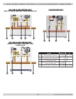
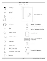
Page 9: ...ION FILL FLOW CHECK VALVE BYPASS VALVE DIVERTER VALVE T P OR RELIEF VALVE THERMOSTATIC MIXING VALVE DHW INDIRECT TANK INDIRECT TANK AQUASTAT 10K Ω INDIRECT DHW TANK SENSOR TEMPERATURE PRESSURE GAUGE EXPANSION TANK FLAT PLATE HEAT EXCHANGER COMBI ONLY STRAINER PIPING LEGEND PURGE VALVE MAGNETIC DIRT SEPARATOR ...

Page 10: ...3 15 2022 75F 100F 125F W ZONE CIRCULATORS DHW TANK PIPING DIAGRAM 75F 100F 125F W ZONE CIRCULATORS DHW TANK PIPING DIAGRAM 1 Shut off Purge Valve MAGNETIC DIRT SEPARATOR 1 Locate shut off valve after any field installed LWCO ...

Page 11: ... sensor to a Heating Only Boiler change P03 from 08 to 05 See Section 9 Parameter Settings in Boiler Installation Operation Maintenance Manual for details Reference zone control manufacturer instructions for details on setting priority if necessary 75F 100F 125F WITH INDIRECT ZONE CIRCULATORS DHW TANK W SENSOR ARGO UZ3 ZONE CONTROL UZ3 ...

Page 12: ...ler Installation Operation Maintenance Manual for details ZONE 1 LINE 24V Vac L C R 115 Vac N L 1 N 115 COM Vac ZR ZC N L 3 N L 2 115 Vac N L 1 L N ZONE CIRCULATOR X X X X X 3 2 1 X NEC Class 2 Low Voltage ZONE 3 ZONE 2 ZONE 1 W R NEC Class 2 Low Voltage T T C THERMOSTATS ZONE VALVES ZONE 3 ZONE 2 4 3 2 1 4 3 2 1 4 3 2 1 NEC Class 2 Low Voltage 24Vac W R T T C W R T T C PRI PUMP ZC ZR DIGITAL LCD ...

Page 13: ...5 REV D 03 15 2022 1 Shut off Purge Valve MAGNETIC DIRT SEPARATOR 75F 100F 125F WITH ZONE VALVES DHW TANK PIPING DIAGRAM 75F 100F 125F WITH ZONE VALVES DHW TANK 1 Locate shut off valve after any field installed LWCO ...

Page 14: ... DHW TANK W SENSOR ARGO UZ3 ZONE CONTROL UZ3 If adding an indirect tank with sensor to a Heating Only Boiler change P03 from 08 to 05 See Section 9 Parameter Settings in Boiler Installation Operation Maintenance Manual for details Reference zone control manufacturer instructions for details on setting priority if necessary ...

Page 15: ...ss 2 Low Voltage 24Vac W R T T C W R T T C PRI PUMP ZC ZR DIGITAL LCD USER DISPLAY Fuse ZONE MODULE TO EXPANSION Transformer PTC 12A 250V Domestic Hot 115 Vac FIELD SUPPLIED POWER PER NEC AND LOCAL CODES Water Tank PRIMARY PUMP ZONE THERMOSTATS ZONE VALVES VANNES DE ZONE 4 Wire Valve 3 Wire Valve 1 2 3 4 1 2 3 w T Stat 1 2 3 4 5 6 7 8 9 10 VAC 24 M2 G UZ3 Reference zone control manufacturer instru...

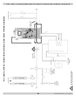
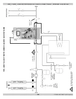
Page 16: ...6 PN 240012875 REV D 03 15 2022 1 Shut off Purge Valve MAGNETIC DIRT SEPARATOR 165F WITH ZONE CIRCULATORS PIPING DIAGRAM 1 Locate shut off valve after any field installed LWCO 165F WITH ZONE CIRCULATORS ...

Page 17: ... 3 2 1 4 3 2 1 4 3 2 1 NEC Class 2 Low Voltage 24Vac W R T T C W R T T C PRI PUMP ZC ZR DIGITAL LCD USER DISPLAY Fuse ZONE MODULE TO EXPANSION Transformer PTC 12A 250V Domestic Hot 115 Vac FIELD SUPPLIED POWER PER NEC AND LOCAL CODES DHW Z2 Z3 Water Tank ZONE THERMOSTATS w T Stat 1 2 3 4 5 6 7 8 9 10 VAC 24 M2 G UZ3 Reference zone control manufacturer instructions for details on setting priority i...

Page 18: ...18 PN 240012875 REV D 03 15 2022 1 Shut off Purge Valve MAGNETIC DIRT SEPARATOR 165F WITH ZONE VALVES 165F WITH ZONE VALVES PIPING DIAGRAM 1 Locate shut off valve after any field installed LWCO ...

Page 19: ...essary ZONE 1 LINE 24V Vac L C R 115 Vac N L 1 N 115 COM Vac ZR ZC N L 3 N L 2 115 Vac N L 1 L N ZONE CIRCULATOR X X X X X 3 2 1 X NEC Class 2 Low Voltage ZONE 3 ZONE 2 ZONE 1 W R NEC Class 2 Low Voltage T T C THERMOSTATS ZONE VALVES ZONE 3 ZONE 2 4 3 2 1 4 3 2 1 4 3 2 1 NEC Class 2 Low Voltage 24Vac W R T T C W R T T C PRI PUMP ZC ZR DIGITAL LCD USER DISPLAY Fuse ZONE MODULE TO EXPANSION Transfor...

Page 20: ...2875 REV D 03 15 2022 115F 150F 205F WITH ZONE CIRCULATORS 115F 150F 205F WITH ZONE CIRCULATORS PIPING DIAGRAM MAGNETIC DIRT SEPARATOR 1 Shut off Purge Valve 1 Locate shut off valve after any field installed LWCO ...

Page 21: ...TOR X X X X X 3 2 1 X NEC Class 2 Low Voltage ZONE 3 ZONE 2 ZONE 1 W R NEC Class 2 Low Voltage T T C THERMOSTATS ZONE VALVES ZONE 3 ZONE 2 4 3 2 1 4 3 2 1 4 3 2 1 NEC Class 2 Low Voltage 24Vac W R T T C W R T T C PRI PUMP ZC ZR DIGITAL LCD USER DISPLAY Fuse ZONE MODULE TO EXPANSION Transformer PTC 12A 250V 115 Vac FIELD SUPPLIED POWER PER NEC AND LOCAL CODES Z2 Z3 ZONE THERMOSTATS 1 2 3 4 5 6 7 8 ...

Page 22: ...240012875 REV D 03 15 2022 115F 150F 205F WITH ZONE VALVES 115F 150F 205F WITH ZONE VALVES PIPING DIAGRAM 1 Locate shut off valve after any field installed LWCO 1 Shut off Purge Valve MAGNETIC DIRT SEPARATOR ...

Page 23: ...ZONE 3 ZONE 2 ZONE 1 W R NEC Class 2 Low Voltage T T C THERMOSTATS ZONE VALVES ZONE 3 ZONE 2 4 3 2 1 4 3 2 1 4 3 2 1 NEC Class 2 Low Voltage 24Vac W R T T C W R T T C PRI PUMP ZC ZR DIGITAL LCD USER DISPLAY Fuse ZONE MODULE TO EXPANSION Transformer PTC 12A 250V 115 Vac FIELD SUPPLIED POWER PER NEC AND LOCAL CODES ZONE THERMOSTATS ZONE VALVES VANNES DE ZONE 4 Wire Valve 3 Wire Valve 1 2 3 4 1 2 3 4...

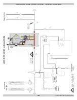
Page 24: ...ffer Tank Piping When installing low mass systems additional water mass may be required to avoid short cycling by the boiler In these applications it is recommended that a buffer tank be installed H2O Stainless Steel Buffer Tank MAGNETIC DIRT SEPARATOR PURGE VALVE Cut Manifold Use Stubs To Connect To Boiler Increase Pipe Size to Match Buffer Tank Connections Buffer Tank on Central Heat Circuit Usi...

Page 25: ... Buffer Tank PURGE VALVE CH System Pump Optional Indirect Tank ZONE PUMPS OR ZONE VALVES MAGNETIC DIRT SEPARATOR 1 2 NOTE Acceptable primary pump locations Either 1 or 2 For pump wiring see diagrams on pages 26 29 Buffer Tank On Central Heat Circuit With Primary Pump and Supplied Manifold ...

Page 26: ...26 PN 240012875 REV D 03 15 2022 EXTERNAL BUFFER TANK WIRING DIAGRAM Buffer Tank Pump Wiring Controlling A Primary Pump On A Combi Boiler With Zone Valves No Indirect Tank ...

Page 27: ...27 PN 240012875 REV D 03 15 2022 EXTERNAL BUFFER TANK WIRING DIAGRAM Buffer Tank Pump Wiring Controlling A Primary Pump On A Combi Boiler With Zone Pumps Argo ARM 4P Zone Control and A822 II ...

Page 28: ...ow Voltage ZONE 3 ZONE 2 ZONE 1 W R NEC Class 2 Low Voltage T T C THERMOSTATS ZONE VALVES ZONE 3 ZONE 2 4 3 2 1 4 3 2 1 4 3 2 1 NEC Class 2 Low Voltage 24Vac W R T T C W R T T C PRI PUMP ZC ZR DIGITAL LCD USER DISPLAY Fuse ZONE MODULE TO EXPANSION Transformer PTC 12A 250V Buffer Tank 115 Vac FIELD SUPPLIED POWER PER NEC AND LOCAL CODES PRIMARY PUMP ZONE THERMOSTATS ZONE VALVES VANNES DE ZONE 4 Wir...

Page 29: ... 1 268 10 4 5 046 68 0 1 218 12 2 4 804 69 8 1 170 14 0 4 574 71 6 1 125 15 8 4 358 73 4 1 081 17 6 4 152 75 2 1 040 19 4 3 958 77 0 1 000 21 2 3 774 78 8 962 23 0 3 600 80 6 926 24 8 3 435 82 4 892 26 6 3 279 84 2 858 28 4 3 131 86 0 827 30 2 2 990 87 8 796 32 0 2 857 89 6 767 33 8 2 730 91 4 740 35 6 2 610 93 2 713 37 4 2 496 95 0 687 39 2 2 387 96 8 663 41 0 2 284 98 6 640 42 8 2 186 100 4 617 ...

Page 30: ...ed and actual outside air temperature Refer to applicable F or C chart pg 30 for setpoint information Select Kt range which will satisfy the desired boiler delivery temperature based on outdoor temperature range expected for your location For example if you need 176 F water when the outside temperature is 20 F and colder select 35 for your Kt setting To change default Kt value on boiler control us...

Page 31: ...d Maintenance Manual Parameter PO3 for COMBI boiler factory set at OO requires no change To activate the 0 10v function parameter 82 must be set to 3 There must be at or above 3 V DC present for the control to recognize a call for heat When P78 1 the 0 10v input manages CH heating setpoint directly per chart below When P78 2 the 0 10v input manages CH heating input directly per chart below When P7...

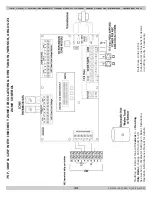
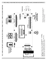
Page 32: ...32 PN 240012875 REV D 03 15 2022 CIRCULATOR CONNECTIONS WIRING DIAGRAM SINGLE ZONE CIRCULATOR WIRING USING ARGO AR822 II ...

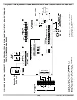
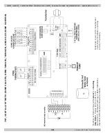
Page 33: ...33 PN 240012875 REV D 03 15 2022 MODEL 75 100 HEAT ONLY 75 100 HEAT ONLY WIRING DIAGRAM ...

Page 34: ...34 PN 240012875 REV D 03 15 2022 MODEL 125 HEAT ONLY 125 HEAT ONLY WIRING DIAGRAM ...

Page 35: ...35 PN 240012875 REV D 03 15 2022 MODEL 165 HEAT ONLY 165 HEAT ONLY WIRING DIAGRAM ...

Page 36: ...36 PN 240012875 REV D 03 15 2022 115 COMBI WIRING DIAGRAM MODEL 115 COMBI ...

Page 37: ...37 PN 240012875 REV D 03 15 2022 MODEL 150 COMBI 150 COMBI WIRING DIAGRAM ...

Page 38: ...38 PN 240012875 REV D 03 15 2022 MODEL 205 COMBI 205 COMBI WIRING DIAGRAM ...

Page 39: ...ER INPUT BTUH ALTITUDE FEET MAC 115 CALCULATEDEFFECTS OF HI ALTITUDE ON BOILER PERFORMANCE DHW MODE HEAT MODE Net Rating Heat Mode MODELS 100 115 40 000 45 000 50 000 55 000 60 000 65 000 70 000 75 000 80 000 0 1 000 2 000 3 000 4 000 5 000 6 000 7 000 8 000 9 000 10 000 BOILER INPUT BTUH ALTITUDE FEET MODEL 75 CALCULATED EFFECTS OF HI ALTITUDE ON BOILER PERFORMANCE HEAT MODE Net Rating Heat Mode ...

Page 40: ...LATED EFFECTS OF HI ALTITUDE ON BOILER PERFORMANCE DHW MODE HEAT MODE NET RATNG HEAT MODE 60 000 80 000 100 000 120 000 140 000 160 000 180 000 200 000 220 000 0 2 000 4 000 6 000 8 000 10 000 BOILER INPUT BTUH ALTITUDE FEET MODELS 165 205 CALCULATED EFFECTS OF HI ALTITUDE ON BOILER PERFORMANCE DHW MODE HEAT MODE NET RATNG HEAT MODE ALTITUDE EFFECTS ON BOILER PERFORMANCE ...

Page 41: ...50 215 116 000 14 0 5 6 H2OI50 196 254 151 231 125 000 14 0 6 2 H20I60 231 298 177 244 132 000 14 0 6 4 H20I60L 211 272 157 218 118 000 14 0 5 9 H2OI80 241 306 169 234 127 000 14 0 6 2 H2OI115 291 363 188 260 141 000 14 0 6 7 High Output Units 60HO 80HO and 115HO H2OI60HO 353 468 299 414 221 000 14 0 10 5 H2OI80HO 366 479 294 407 220 000 14 0 10 3 H2OI80HOC 386 507 314 435 236 000 21 0 15 8 H2OI15...

Page 42: ...EC or Canadian Electrical Code CEC Locate LWCO sensing device in the supply piping above the minimum height of boiler See Figure page 42 Piping Diagram Position control in piping above boiler to assure proper boiler protection For proper operation sensing element of the LWCO control shall be positioned in the tee to sense the main water stream Maintain minimum 1 4 spacing from pipe walls Element s...

Page 43: ...onto boiler Illustrations are meant to show system piping concept only Installer is responsible for all equipment and detailing required by authority having jurisdiction Air Vent Supply Gas Boiler Safety Relief Valve Position LWCO Above Top of Boiler To Drain Check Local Codes for Maximum Distance to Floor 1 Return Magnetic Dirt Separator Purge Valve Purge Valve 1 Note Note ...

Page 44: ...44 PN 240012875 REV D 03 15 2022 LOW WATER CUTOFF LOW WATER CUTOFF DETAIL NO NO YES ...

Page 45: ...Ground Short Circuit and Polarity with a suitable meter NOTE These checks must be repeated after any servicing or fault finding 5 Ensure all external controls are calling for heat and check all external and internal fuses Before any servicing or replacement of parts ensure the gas and electrical supplies are isolated 1 If a fault occurs on the boiler an error code may show on the fascia display E ...

Page 46: ... Burner lights YES Error E109 flashing NO Error E11O flashing NO 3 way valve open to central heating circuit YES Burner output modulates to maintain the temperature set YES YES YES YES YES Error E130 flashing NO YES Burner goes out YES Go to section I NO NO Ensure all controls and Programmers are calling for heat NO Error 160 flashing Go to section C NO Error 160 flashing Go to section C NO Error ...

Page 47: ...speed YES Spark at ignition electrodes for up to 5 seconds and for 5 attempts YES NO YES Burner lights YES YES Error E109 flashing NO Error E110 flashing YES NO NO NO NO DHW flow rate more than 21 min Error 160 flashing Go to section C Error 160 flashing Go to section C Error 133 flashing Go to section E Burner does not stay alight after 5 seconds Error E125 flashing after 1 minute Go to section H...

Page 48: ...mp terminals Blue to Brown See Wiring Diagram NO Replace PCB Fan connections correct at fan and PCB Connectors X11 X23 See Wiring Diagram YES NO 120V between PCB connector x13 pump terminal Blue and PCB connector x11 pump terminal Black See Wiring Diagram NO Replace PCB Make connections Main or Display PCB fault 120V at Pump NO Check wiring Replace Pump YES YES Is there 120V AC at fan terminals co...

Page 49: ...49 PN 240012875 REV D 03 15 2022 3 FAULT SOLUTION SECTIONS ...

Page 50: ... pcb connection at connector x22 is there approx 5 V DC between the green and black NO terminals Check flow temperature sensor connections and position Sensors swapped Cold resistance approximately 1OkO 77 F CH sensors resistance reduces with increase in temp YES I I I I Is E11O is still flashing Replace pressure sensor Replace PCB I Replace sensor Go to section B Is there 120V at PCB connector x1...

Page 51: ... terminals Check the voltage is approximately 5 VDC between the Red and Blue wires See Wiring Diagrams With water running through DHW circuit measure red and white wire for 2 8 VDC for flow triggering Check DHW NTC senor for proper OHM value Replace PCB YES YES YES YES Clean or Replace Replace PCB Replace Hall Effect Sensor Replace DHW NTC sensor NO NO NO NO ...

Page 52: ...Changed From Changed To Date Reason PARAMETER CHANGE HISTORY All specifications subject to change without notice 2022 ECR International Inc 2201 Dwyer Avenue Utica NY 13501 Tel 800 325 5479 www ecrinternational com ...

Reviews: