45
PN 240012875 REV. D [03/15/2022]
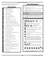
ERROR CODE TABLE
E
09
Gas Valve Connection Cable
E
10
External Probe Fault
E
12
Water Flow Switch Open
E
13
Water Flow Switch Close
E
15
Gas Valve Fault
E
18
Water Refill Enabled
E
19
Max Time Of Water Refill
E
20
Central Heating Flow NTC Fault
E
28
Flue NTC Fault
E
40
Central Heating Return NTC Fault
E
50
Hot Water NTC Fault (tank version)
E
53
Obstruction on flue pipe-combustiion off
E
55
PCB to be set by the “Calibration Function”
E
71
Fan parameter Out of range in auto calibration
E
72
Combustion test out of range in auto calibration
E
77
Current Out of range
E
78
Minimum gas valve current
E
79
Maximum gas valve current
E
83-87 Communication error
E
92
Combustion test alarm during auto-setting
E
109 Pre-Circulation Fault
E
110 Safety Thermostat Operated
E
117 System Water Pressure To High
E
118 System Water Pressure To Low
E
125 Circulation Fault (Primary Circuit)
E
128 Flame Failure
E
129 Frequent loss of flame during ignition
E
130 Flue NTC Operated
E
133 Interruption of Gas Supply or Flame Failure
E
134 Elapsed time Gas valve open without gas
E
135 Interruption of gas supply (internal error)
E
160 Fan or Fan Wiring Fault
E
321 Domestic Hot Water NTC sensor fault
E
384 False flame
E
385 Under voltage
Note:
When instructed press and hold “RESET” for
between 1-3 seconds to reset the boiler.
Table of Error Codes
1
Check gas, water and electrical supplies are available at the
boiler
.
2
Electrical supply = 120V ~60 HZ
3
The preferred minimum gas pressure is 3.5” wc for Natural
gas and 10” for LPG
4
Perform electrical system checks, i.e. Ground Continuity,
Resistance to Ground, Short Circuit and Polarity with a
suitable meter.
NOTE: These checks must be repeated after any servicing
or fault finding.
5
Ensure all external controls are calling for heat and check
all external and internal fuses. Before any servicing or
replacement of parts, ensure the gas and electrical supplies
are isolated.
1 If a fault occurs on the boiler an error code may show on the
fascia display:
E
20,
E
28,
E
40,
E
50,
E
160,
E
321, and
E
431 -
Indicate
possible faulty components.
E
53 -
Indicates possible obstruction in the flue duct.
E
55 -
Indicates the PCB is not setting/calibrated.
E
71,
E
72,
E
78 and
E
92 -
Indicates possible wrong
calibration, a new calibration is needed.
E
92
- Indicates possible flue recirculation in the flue duct.
E
83......87 - Shows possible error of communication with
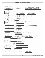
thermostat. (Go to section P, page 47)
E
110 -
Shows overheat of primary.
E
117 - is displayed when the primary water pressure is
more than 43 psi.
E
118 - is displayed when the primary water pressure is less
than 7.25 psi.
E
125
-
is displayed in either of two (2) situations:
a)
If within a time between 15...30 seconds of the burner
lighting the boiler temperature has not changed by 2°F.
b)
If within 10 minutes of the burner lighting the boiler
temperature twice exceeds the selected temperature by
80°F.
In these instances poor primary circulation is indicated.
E
128 - is displayed if there has been a flame failure during
normal burner operation.
E
133
,
E
134
,
E
135
-
Indicate the gas supply has been
interrupted, ignition has failed or flame has not been
detected.
2
Pressing the ‘RESET’ button for 1-3 seconds when:
E
110,
E
125,
E
133,
E
134,
E
135,
E
09,
E
15,
E
128 and
E
384 - are displayed it is possible to relight the boiler.
3
If this does not have an effect, or error codes are displayed
regularly further investigation is required.
Initial Fault Finding Checks
Summary of Contents for 100F
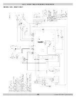
Page 33: ...33 PN 240012875 REV D 03 15 2022 MODEL 75 100 HEAT ONLY 75 100 HEAT ONLY WIRING DIAGRAM ...
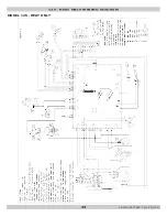
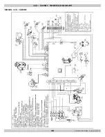
Page 34: ...34 PN 240012875 REV D 03 15 2022 MODEL 125 HEAT ONLY 125 HEAT ONLY WIRING DIAGRAM ...
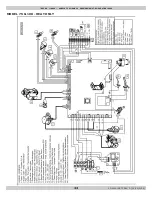
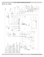
Page 35: ...35 PN 240012875 REV D 03 15 2022 MODEL 165 HEAT ONLY 165 HEAT ONLY WIRING DIAGRAM ...
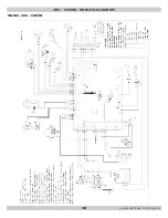
Page 36: ...36 PN 240012875 REV D 03 15 2022 115 COMBI WIRING DIAGRAM MODEL 115 COMBI ...
Page 37: ...37 PN 240012875 REV D 03 15 2022 MODEL 150 COMBI 150 COMBI WIRING DIAGRAM ...
Page 38: ...38 PN 240012875 REV D 03 15 2022 MODEL 205 COMBI 205 COMBI WIRING DIAGRAM ...
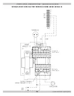
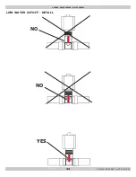
Page 44: ...44 PN 240012875 REV D 03 15 2022 LOW WATER CUTOFF LOW WATER CUTOFF DETAIL NO NO YES ...
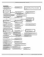
Page 49: ...49 PN 240012875 REV D 03 15 2022 3 FAULT SOLUTION SECTIONS ...

