7
PN 240012875 REV. D [03/15/2022]
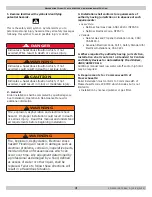
Note
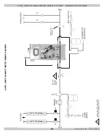
Provided Wiring and Piping illustrations
are meant to show system concepts only.
Installer is responsible for all equipment
required by authority having jurisdiction.
Note
Arrange piping to prevent water dripping
onto boiler.
All piping diagrams are shown with optional DHW Indirect
Tank where applicable.
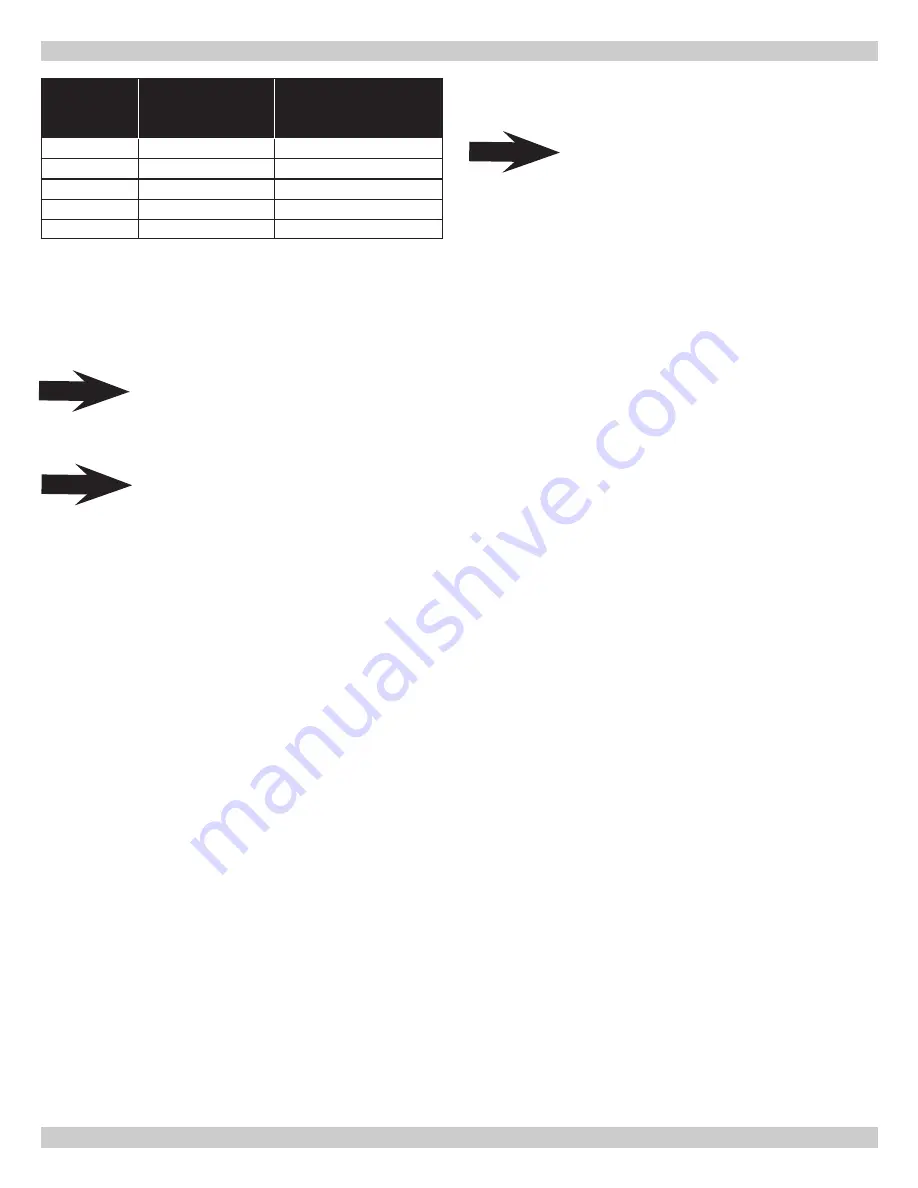
GENERAL INFORMATION - HYDRONIC PIPING
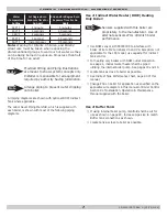
Water
Temperature
Setting
1st Degree Burn
Exposure Time For
An Adult
2nd and 3rd Degree Burn
Exposure Time For An
Adult
120° F
1 minute
5 minutes
130° F
5 seconds
30 seconds
140° F
2 seconds
5 seconds
150° F
1 second
1.5 seconds
160° F
Instantaneous
0.5 seconds
Note:
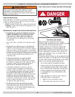
Warning for Infants, Children, and Elderly:
Great care must be taken when exposing the
aforementioned groups to warm or hot water as they
can be badly burned in exposure times less than half
of the time for an adult.
Use of Buffer Tank:
☐
If using internal boiler pump, manifold shall be cut for
use as shown on page 24. Increase pipe size to match
Buffer tank connections as shown.
☐
Locate tank as close to boiler as possible.
The Labor Saver Piping Manifold, which is supplied with
each boiler, is shown with most of the following piping
diagrams.
Use of Indirect Water Heater (DHW) Heating
Only Boiler:
Note
Sensors supplied with this boiler are
proprietary to the manufacturer. Use of
alternate sensors
WILL
diminish boiler
performance.
☐
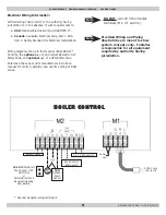
Use DHW sensor kit 550003189 to interface with
boiler. Wire to M2 terminals #3 and #4. Exception: not
applicable for the 165 model, use aquastat for indirect
tank control.
☐
For heating only boilers with DHW outlet connection,
see page 4, indirect water heater shall be piped
utilizing the internal boiler pump. See pages 10 and 13.
☐
Locate tank as close to boiler as possible.
☐
See Indirect Tank Performance chart, page 40 of this
manual.
☐
Change P03 on boiler for application as specified on the
applicable wire diagram in this manual or Boiler Control
Section 9 of Installation, Operation & Maintenance
Manual supplied with the boiler.
Summary of Contents for 100F
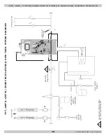
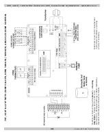
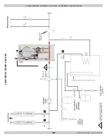
Page 33: ...33 PN 240012875 REV D 03 15 2022 MODEL 75 100 HEAT ONLY 75 100 HEAT ONLY WIRING DIAGRAM ...
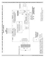
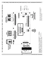
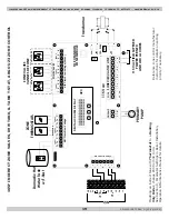
Page 34: ...34 PN 240012875 REV D 03 15 2022 MODEL 125 HEAT ONLY 125 HEAT ONLY WIRING DIAGRAM ...
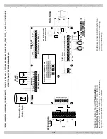
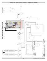
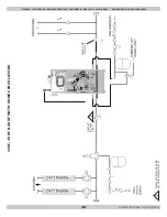
Page 35: ...35 PN 240012875 REV D 03 15 2022 MODEL 165 HEAT ONLY 165 HEAT ONLY WIRING DIAGRAM ...
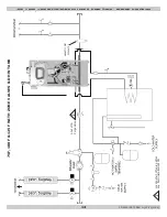
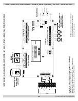
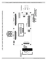
Page 36: ...36 PN 240012875 REV D 03 15 2022 115 COMBI WIRING DIAGRAM MODEL 115 COMBI ...
Page 37: ...37 PN 240012875 REV D 03 15 2022 MODEL 150 COMBI 150 COMBI WIRING DIAGRAM ...
Page 38: ...38 PN 240012875 REV D 03 15 2022 MODEL 205 COMBI 205 COMBI WIRING DIAGRAM ...
Page 44: ...44 PN 240012875 REV D 03 15 2022 LOW WATER CUTOFF LOW WATER CUTOFF DETAIL NO NO YES ...
Page 49: ...49 PN 240012875 REV D 03 15 2022 3 FAULT SOLUTION SECTIONS ...


