28141 Rev A 10-27-06
5
furnace and should not interfere with the
combustion air supplied to the burner. The control
should also be located near the furnace flue outlet
and installed according to the instructions
supplied with the regulator. The over fire draft
should be set to -0.02 in. w.c.
8. OPTIONAL SIDEWALL VENTING
BFL and BCL Model furnaces designated with a
"U" are Sidewall Vent units and shall be installed
with sidewall venting components provided.
Please refer to the Direct Sidewall Vent
Instructions, Part No. 28888, included with the
appropriate Vent Kit for details. Through the wall,
(Sidewall Venting or Direct Sidewall Venting)
requires the use of specific oil burners; the
Beckett AFII, or the Riello BF series. Please refer
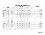
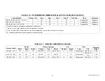
to Appendix A, Tables A2, and A6.
Note: Sidewall venting requires special attention
to combustion air supply. There is no natural draft
in the venting system between furnace cycles;
therefore, if the indoor pressure is negative
relative to the outdoors, the vent terminal
becomes a point of infiltration. This could lead to
oil odour control problems. This may be rectified
by the use of ducted outdoor air for combustion
(sealed combustion), using the Beckett AFII or
Riello BF Series oil burner.
BCL-80S through BCL-145S and BFL-80 through
BFL-145 are approved for use with the Field
Controls Co. Models SWGII-5 and PVE-5 power
venters. This venting option is not recommended
as an equal alternative to chimney venting
because the outlet terminal becomes a major
point of infiltration between furnace cycles,
occasionally resulting in oil odour control
problems. The SWG and PVE power venter kits
are available through major HVAC supply
companies. SWG and PVE technical support is
offered by their manufacturer; not by ECR
International Ltd. - Olsen Division
9. FAN AND LIMIT CONTROL
The
L6064A
temperature sensitive fan switch is
actuated by a helical bi-metal sensing element
enclosed in a metal guard, and controls the
circulating air blower. This provides a delay
between the burner ignition and blower start up to
eliminate excessive flow of cold air when the
blower comes on. Blower shutdown is also
delayed to remove any residual heat from the
heat exchanger and improve the annual efficiency
of the furnace. Fan on settings of 110º F to 130º F
(43º C to 55º C) and fan off settings of 90º F to
100º F (32º C to 37ºC) will usually be satisfactory.
The
L4064W
temperature sensitive fan switch
contains a heater-wrapped bi-metal to actuate the
fan switch independent of the temperature at the
helical sensing element. The time from ignition, to
the blower on function is approximately 30
seconds. If after 1 minute, the blower has not
come on, replacement of the control may be
necessary. The blower shutdown is the same as
noted for the L6064A control.
The limit switch performs a safety function and
breaks power to the oil burner primary control,
which shuts off the burner if the furnace over-
heats. The limit control is thermally operated and
automatically resets. The limit control is factory
installed, pre-set and is not adjustable.
The limit control and fan control are incorporated
in the same housing and are operated by the
same thermal element.
10. ELECTRICAL CONNECTIONS
The furnace is listed by CSA to the North
American standard. The furnace is factory wired
and requires minimal field wiring. All field wiring
should conform to CAN/CSA C22.1 Canadian
Electrical Code, Part 1, and by local codes, where
they prevail. In the United States, the wiring must
be in accordance with the National Fire Protection
Association NFPA-70, National Electrical Code,
and with local codes and regulations.
The furnace should be wired to a separate and
dedicated circuit in the main electrical panel;
however, accessory equipment such as electronic
air cleaners and humidifiers may be included on
the furnace circuit. Although a suitably located
circuit breaker can be used as a service switch, a
separate service switch is advisable. The service
switch is necessary if reaching the circuit breaker
involves becoming close to the furnace, or if the
furnace is located between the circuit breaker and
the means of entry to the furnace room. The
furnace switch (service switch) should be clearly
marked, installed in an easily accessible area
between the furnace and furnace room entry, and
be located in such a manner to reduce the
likelihood that it would be mistaken as a light
switch or similar device.
Summary of Contents for BCL
Page 23: ...28141 Rev A 10 27 06 23 TABLE B 1 BECKETT AND RIELLO CHIMNEY VENTED WIRING DIAGRAM BCL S BFL ...
Page 24: ...28141 Rev A 10 27 06 24 TABLE B 2 BECKETT AND RIELLO DIRECT VENT WIRING DIAGRAM BCL S BFL ...
Page 29: ...29809 Rev A 10 19 2006 29 ...
Page 32: ...29809 Rev A 10 19 2006 32 ...
Page 36: ...29809 Rev A 10 19 2006 36 ...
Page 41: ...28141 Rev A 10 27 06 NOTES ...
Page 42: ...28141 Rev A 10 27 06 ...
Page 43: ...28141 Rev A 10 27 06 ...


