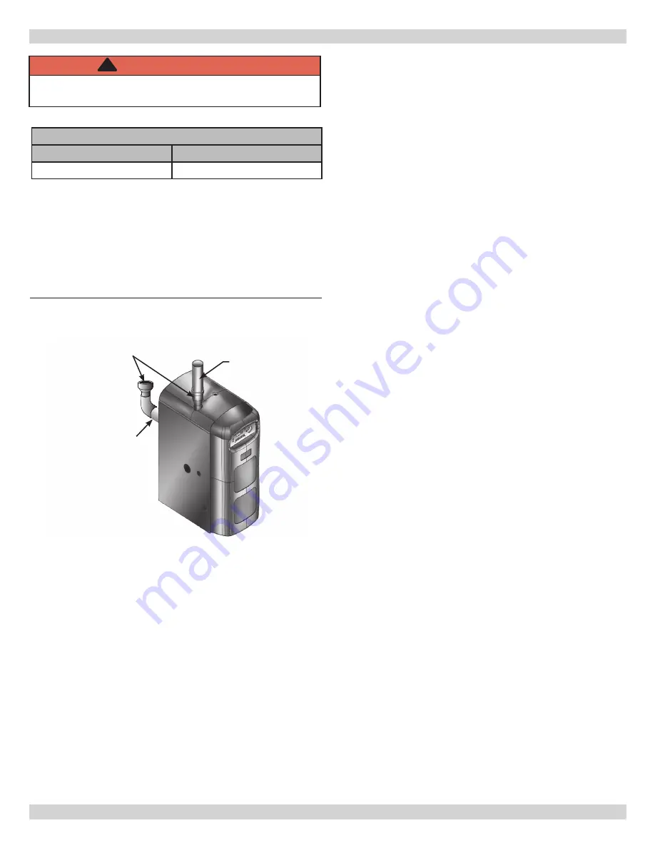
8 - COMBUSTION AIR AND VENT PIPE
Allowable Vent and Air Intake Lengths
3” Pipe Min. Length
3” Pipe Max. Length
15 ft. equivalent length
100 ft. equivalent length
FIELD INSTALL 2” BY 3”
TRANSITION IN THE
VERTICAL POSITION
ONLY (2 REQ’D, NOT
FURNISHED)
3” INTAKE AND
EXHAUST
TERMINATIONS
2” (50.8MM)
CPVC
VENT PIPING
(FURNISHED &
REQUIRED)
2” (50.8MM)
COMBUSTION AIR
INTAKE PIPING
(FURNISHED)
Figure 4 - Combustion Air & Vent Piping
9.
Combustion air must be clean outdoor air. Do not take
combustion air from inside structure because that air
is frequently contaminated by halogens, which includes
fluorides, chlorides, phosphates, bromides and iodides.
These elements are found in aerosols, detergents,
bleaches, cleaning solvents, salts, air fresheners, paints,
adhesives, and other household products.
10.
Locate combustion air inlet as far away as possible from
swimming pool and swimming pool pump house.
11.
All combustion air and vent pipes must be airtight and
watertight.
12.
Pitch exhaust air piping back to boiler at minimum ¼” per
foot from vent terminals so all moisture in vent piping
drains to boiler. Pitch pipes with no sags or low spots
where moisture can accumulate and block flow of flue gas.
13.
Vent connections serving appliances vented by
natural draft shall not be connected into any portion
of mechanical draft systems operating under positive
pressure.
8.2 Vent/Air Intake Termination Location
Consider following when determining appropriate location
for termination of combustion air and vent piping.
A. Position termination where vent vapors will not
damage plants/shrubs, air conditioning equipment, or
siding on the house.
B. Position termination so it will not be effected by wind
eddy, air born leaves, snow, or recirculated flue gases.
C. Position termination where it will not be subjected to
potential damage by foreign objects, such as stones,
balls, etc.
D. Position termination where vent vapors are not
objectionable.
E. Put vent on wall away from prevailing winter wind.
Locate or guard vent to prevent accidental contact
with people or pets.
F. Terminate vent above normal snow-line. Avoid locations
where snow may drift and block vent. Ice or snow may
cause boiler to shut down if vent becomes obstructed.
G. Under certain conditions, flue gas will condense,
forming moisture, and may be corrosive. In such
cases, take steps to prevent building materials at
vent from being damaged by exhaust of flue gas.
H. United States - Terminate vent system at least 4
feet (1.22 m) horizontally from, and in no case
above or below, unless a 4 feet (1.22 m) horizontal
distance is maintained, from electric meters, gas
meters, regulators and relief equipment.
I. Canada - Terminate vent system at least 6 feet
(1.83m) horizontally from, and in no case above
or below, unless 6 feet (1.83m) horizontal distance
is maintained, from electric meters, gas meters,
regulators and relief equipment.
J. Terminate venting system at least 3 feet (0.3m)
above any forced air inlet (except boiler’s
combustion air inlet) within 10 feet (3m).
K. Terminate venting system at least 12 inches
(300mm) from any air opening into any building.
L. Locate bottom of vent at least 12 inches (300mm)
above grade.
M. Terminate vent not less than 7 feet (2.1m) above
adjacent public walkway.
N. Vent terminal shall not be installed closer than 3 feet
(0.9m) from inside corner of L shaped structure.
O. Termination of vent should be kept at least 3 feet
(0.9m) away from vegetation.
P. If multiple terminations are used, minimum of
12 inches (300 mm) between exhaust of one
termination and air intake of next termination. See
pages 14 & 15.
Q. All field installed vent pipe must be 3”.
Length of pipe is counted from end of supplied 2” CPVC
pipe exiting boiler. Termination is not counted in “Total
Equivalent Length.”
Reduce maximum vent/air intake length by 5 feet per each
90° elbow.
WARNING
Covering non-metallic vent pipe and fittings with
thermal insulation shall be prohibited.
!
13
Summary of Contents for Dunkirk Q95M-200
Page 2: ...1 DIMENSIONS OPENING FOR SAFETY RELIEF VALVE DISCHARGE PIPE 30 785mm 39 1 1m 18 458mm 2 ...
Page 27: ...APPENDIX A BOILER PIPING AND WIRING Electrical Wiring Diagram 27 ...
Page 49: ...49 NOTES ...
Page 50: ...50 NOTES ...
Page 51: ...51 Company Address Phone Company Name Tech Initials Service Performed Date SERVICE RECORD ...


