background image

BOILER

WATER INLET

ALTERNATE

CIRCULATOR

LOCATION

TO SYSTEM

FROM SYSTEM

CIRCULATOR

SHUT-OFF

VALVE

PRESSURE

REDUCER VALVE

CHECK VALVE

BALL VALVE

3 WAY MIXING

VALVE

AIR SEPARATOR

HOSE BIB

EXPANSION

TANK

BOILER

ALTERNATE

CIRCULATOR

LOCATION

TO SYSTEM

FROM SYSTEM

V2

V1

CIRCULATOR

SHUT-OFF

VALVE

PRESSURE

REDUCER VALVE

CHECK VALVE

BALL VALVE

AIR SEPARATOR

ZONE VALVE

EXPANSION

TANK

WATER INLET

SYSTEM

CIRCULATOR

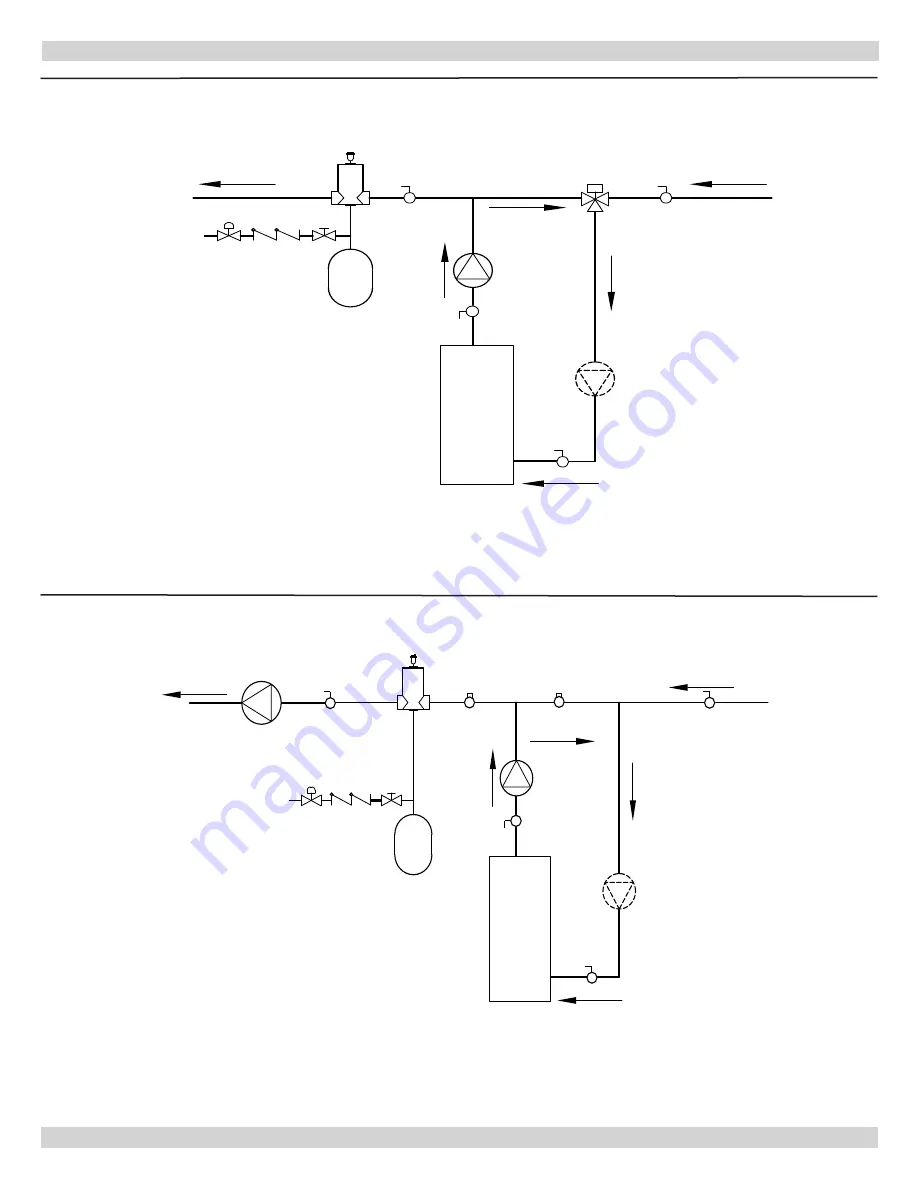
Piping Diagram 8 : Bypass Piping (Automatic Mixing Valve)

Piping Diagram 9 : Bypass Piping (Fixed Low Temp Only)

APPENDIX A - BOILER PIPING AND WIRING

42

Summary of Contents for Dunkirk Q95M-200

Page 1: ... HOT WATER BOILER INSTALLATION OPERATION MAINTENANCE MANUAL An ISO 9001 2008 Certified Company Manufactured by ECR International Inc 2201 Dwyer Avenue Utica NY 13501 web site www ecrinternational com P N 240006103D Rev E 02 2014 Model Q95M 200 ...

Page 2: ...1 DIMENSIONS OPENING FOR SAFETY RELIEF VALVE DISCHARGE PIPE 30 785mm 39 1 1m 18 458mm 2 ...

Page 3: ...at from the cast aluminum heat exchanger cooling flue gases and causing condensation Sealed combustion premix gas burner and low flame temperature means reduced CO and NOx emissions which contribute to cleaner and healthier environment This appliance takes its combustion air directly from outdoors sealed combustion and does not compete with building occupants for fresh air 2 INTRODUCTION Sealed co...

Page 4: ...ments before beginning installation Keep this manual near boiler Retain for future reference 3 2 Installation shall conform to requirements of authority having jurisdiction or in absence of such requirements United States National Fuel Gas Code ANSI Z223 1 NFPA 54 National Electrical Code NFPA 70 Canada Natural Gas and Propane Installation Code CAN CSA B149 1 and 2 Canadian Electrical Code Part I ...

Page 5: ...d above Heating Capacity indicates amount of heat available after subtracting losses up the stack Most of this heat is available to heat water Small portion is heat loss from jacket and boiler surfaces and it is assumed this heat stays in the structure Net AHRI Rating represents portion of remaining heat that can be applied to heat radiation or terminal units i e finned tube baseboard cast iron ra...

Page 6: ...rly located thermostat or operating control not included with boiler WARNING Fire hazard Do not install on carpeting Failure to follow these instructions could result in death or serious injury Placed on level surface must NOT be installed on carpeting Pitch condensate drain line down to floor drain or external condensate pump with reservoir at per foot wood frame or blocks may be used to raise bo...

Page 7: ... are required to venting or combustion air intake piping 6 Install equipment in location which facilitates operation of venting and combustion air intake piping systems as described in this manual 7 Advise owner to keep venting and combustion air intake passages free of obstructions Both venting and combustion air intake piping systems connected to outdoors must permit flow through piping systems ...

Page 8: ...From Common Vent System When an existing boiler is removed from a common venting system the common venting system is likely to be too large for proper venting of the appliances remaining connected to it At the time of removal of an existing boiler the following steps shall be followed with each appliance remaining connected to the common venting system placed in operation while the other appliance...

Page 9: ...lder systems obviously discolored murky or dirty water or pH reading outside acceptable range between 7 0 and 8 0 are indications system should be cleaned or treated Thoroughly flush system with clean water to remove any sediment or contaminants Sludge and iron oxide deposits can cause rapid breakdown of inhibitors Flushing with clean water If chemical cleaners are used use only those recommended ...

Page 10: ... relief valve outlet Install elbow s if used close to safety relief valve outlet and downstream of union if used Terminate pipe with plain end not threaded 7 4 Expansion Tank Make up Water Determine required system fill pressure system design temperature and system water content Boiler contains 2 6 gallons US Size expansion tank accordingly Consult expansion tank manufacturer for proper sizing inf...

Page 11: ...are steps required to initially fill condensate trap for start up Steps are only required at initial start up or if maintenance requires draining of condensate trap 1 Remove vent drain line from CPVC vent pipe Pour about 1 cup of cold tap water into vent drain line 2 Excess water should go through overflow and out through condensate drain line Verify proper operation of drain line or external cond...

Page 12: ...s of the certified system must not be interchanged with other vent systems or unlisted pipe and or fittings NOTICE Transition from 2 pipe to 3 pipe must be made in vertical run 7 Boiler combustion air and vent pipe connections are 2 but must increase to 3 Due to potential for flue gas temperatures above 155 F first 30 of supplied vent pipe is CPVC while remaining vent pipe can be PVC Any replaceme...

Page 13: ...etc D Position termination where vent vapors are not objectionable E Put vent on wall away from prevailing winter wind Locate or guard vent to prevent accidental contact with people or pets F Terminate vent above normal snow line Avoid locations where snow may drift and block vent Ice or snow may cause boiler to shut down if vent becomes obstructed G Under certain conditions flue gas will condense...

Page 14: ...Figure 5 Side Wall Vent Intake terminations Less Than 12 Clearance Above Grade 8 COMBUSTION AIR AND VENT PIPE 3 MIN SEPARATION 14 ...

Page 15: ...Minimum Maintain 12 300mm clearance above highest anticipated snow level or grade 12 300mm Minimum Must be less than 4 102mm or greater than 24 610mm Horizontal distance between end bells of each air intake to prevent flue gas recirculation Figure 6 Roof Vent Intake Terminations Figure 7 Concentric Vent Terminations 3 MINIMUM SEPARATION 15 ...

Page 16: ...rk insertion depth on pipe 10 After pipes have been cut and pre assembled apply cement primer to pipe fitting socket and end of pipe to insertion mark Quickly apply approved cement to end of pipe and fitting socket over primer Apply cement in light uniform coat on inside of socket to prevent buildup of excess cement Apply second coat 11 While cement is still wet insert pipe into socket with turn t...

Page 17: ... from gas supply piping system by closing its manual shutoff valve during any pressure testing of gas supply piping system at test pressures equal to or less than psig 3 5kPa For proper boiler operation line pressure should be within minimum and maximum values in Table 6 Gas line enters boiler through left side panel See page 2 Dimensions and Figure 10 Boiler is equipped with NPT connection on gas...

Page 18: ...r leak detection method acceptable to authority having jurisdiction Do not use matches candles open flames or other methods providing ignition source Correct leaks immediately and retest 9 GAS SUPPLY PIPING 1 2 GAS CONNECTION NOTE 3 4 GAS SUPPLY TO BOILER JACKET REQUIRED TO FEED THE BOILER DANGER Fire Hazard Do not use matches candles open flames or other methods providing ignition source Failure ...

Page 19: ...ceptable range green light will illuminate on monitor and boiler will restart Line voltage monitor is factory set at 115 VAC It is important that monitor be set to voltage present at installation site by following these directions 1 Using multimeter locate wall outlet nearest to boiler and determine line voltage present on site 2 Disconnect power to boiler 3 Remove boiler cover 4 Locate line volta...

Page 20: ...or reset operation of the boiler If fixed temperature operation is required do not install outdoor sensor 2 Mount sensor on exterior wall shielded from direct sunlight or flow of heat or cooling from other sources 3 If desired install a summer winter switch across terminals A1 and A2 When the switch is closed the boiler space heating circulator is disabled 4 Route sensor wires through the holes pr...

Page 21: ... developed for domestic heating appliances with premix burners and automatic direct burner ignition and are suitable for natural and LP gas Gas controls perform all functions required to safely regulate gas flow to main burner of boiler Gas valve is directly connected to gas air mixer 11 7 Gas Air Mixer Venturi design of gas air ensures correct mixture of air and gas 11 8 Modulating Burner Burner ...

Page 22: ... downstream pumping away side of expansion tank 11 15 Blocked Vent Safety Assembly Blocked vent safety assembly incorporates two pressure switches designed to discontinue operation of boiler if there is a problem with blower or venting system The normally open switch closes upon initiation of blower and functions as air proving switch The normally closed switch opens if there is a blockage in comb...

Page 23: ...al Closed Type Expansion Tanks A Close all zone service valves on supply and return piping and close expansion tank service valve Drain expansion tank Open feed valve and fill boiler with water Hold relief valve open until water runs air free for five seconds to rapidly bleed air from boiler then let relief valve snap shut B Open zone service valve on supply pipe for first zone Open purge valve on...

Page 24: ... supplier 13 OPERATING INSTRUCTIONS Control Valve ON Control Valve OFF Figure 12 Gas Valve 13 1 Lighting Instructions For Your Safety Read Before Operating WARNING If you do not follow these instructions exactly a fire or explosion may result causing property damage personal injury or loss of life This appliance is equipped with an ignition device which automatically lights burner Do NOT try to li...

Page 25: ...top panels check for piping leaks around safety relief valve and other fittings and repair if found Do not use stop leak compounds 2 Verify boiler area is free from combustible materials gasoline and other flammable vapors and liquids 3 Circulator pump and blower fan motor furnished with boiler are permanently lubricated from factory and require no further lubrication Additional or non factory sup...

Page 26: ...ough condensate drain Be wary of drain lines getting clogged and causing water to back up in the bottom of casting H Use flexible handle nylon brush to loosen sediment and aluminum oxide on all accessible heating surfaces of boiler Take care not to get brush stuck in heat exchanger I After brushing and rinsing remove any remaining loosened sediment using shop vacuum with snorkel attachment J Inspe...

Page 27: ...APPENDIX A BOILER PIPING AND WIRING Electrical Wiring Diagram 27 ...

Page 28: ...OOR AIR SENSOR BOILER CONTROL PANEL DHW CIRC L1 120 VAC L2 CH CIRC Note CH DHW Circulator connections on boiler only support pump with 1 amp rating or less Boiler Control Wiring Diagram Single Zone System With Domestic Hot Water Priority APPENDIX A BOILER PIPING AND WIRING 28 ...

Page 29: ...r thermostat Boiler Control Panel DHW CIRC L1 HOT L2 N 120V AC NO L2 VAC 120 4 4 NC AR822 II TORQUE TERMINAL 6 TO 7 INCH LBS ELECTRONIC FUSE CIRCUIT ON AR822 TT R T TT NO 24V W C T 5 SCREWS NC 6 6 CH CIRC Piping Diagram 1 Single Zone System With Domestic Hot Water Priority Wiring Diagram 1 Single Zone System With Domestic Hot Water Priority APPENDIX A BOILER PIPING AND WIRING 29 ...

Page 30: ...NOTE NOT RECOMMENDED FOR ANTIFREEZE APPLICATIONS Piping Diagram 2 Multizone Piping With Zone Valves And Domestic Hot Water Priority With Zone Valve APPENDIX A BOILER PIPING AND WIRING 30 ...

Page 31: ...ZC DPM 2 OPTION SWITCH ZC ON STATUS PRIORITY ON PRIMARY PUMP PRIORITY PUMP X X CONTACT ZR ON T T T T T T T T 1 2 3 4 PRI ZONE 1 2 3 4 ZONE 2 1 2 3 4 ZONE 3 1 2 3 4 ZONE 4 SWITCH LEGEND OFF ON N L N L N L ZR ZC 120 VAC PRIORITY PUMP PRIMARY PUMP FROM BOILER X X TRANSFORMER 24VAC 40 VA L LINE IN N Black White 24VAC N L Yellow Yellow AZ 4CP Boiler Control Panel DHW C1 DHW C2 CH C2 L2 L1 CH C1 CH DHW ...

Page 32: ...NOTE NOT RECOMMENDED FOR ANTIFREEZE APPLICATIONS Piping Diagram 3 Multizone System With Zone Valves And Domestic Hot Water Priority With Circulator APPENDIX A BOILER PIPING AND WIRING 32 ...

Page 33: ...UMP PRIORITY ON ZR ZC DPM 2 OPTION SWITCH ZC ON STATUS PRIORITY ON PRIMARY PUMP PRIORITY PUMP X X CONTACT ZR ON T T T T T T T T 1 2 3 4 PRI ZONE 1 2 3 4 ZONE 2 1 2 3 4 ZONE 3 1 2 3 4 ZONE 4 SWITCH LEGEND OFF ON N L N L N L ZR ZC 120 VAC PRIORITY PUMP PRIMARY PUMP FROM BOILER X X TRANSFORMER 24VAC 40 VA L LINE IN N Black White 24VAC N L Yellow Yellow AZ 4CP Boiler Control Panel DHW C1 DHW C2 CH C2 ...

Page 34: ...NOTE NOT RECOMMENDED FOR ANTIFREEZE APPLICATIONS Piping Diagram 4 Multizone System With Circulators And Domestic Hot Water Priority APPENDIX A BOILER PIPING AND WIRING 34 ...

Page 35: ... 3 R ZONE 4 W T 4 R T DHW CIRC L2 CH C2 DHW C2 DHW C1 DHW T2 A2 A1 DHW T1 CH T2 CH T1 OUTDOOR AIR SENSOR aquastat or thermostat Boiler Control Panel 115 V COIL ISOLATION RELAY NORMALY OPEN NOTE IN PLACE OF 115 VOLT ISOLATION RELAY OPTIONAL CONTROL ARGO AR822II TERMINAL 5 6 N O TO DHW T1 DHW T2 L1 L2 TO ARM L N ON PRIORITY ZONE ELECTRONIC FUSE VAC CIRCUIT ON 120 L2 NO 4 NC 4 AR822 TT SCREWS TORQUE ...

Page 36: ...METER CLOSELY SPACED TEES BOILER PUMP SEE NOTE NOTE RECOMMENDED FOR ANTIFREEZE APPLICATIONS Piping Diagram 5 Primary Secondary Piping With Circulators And Domestic Hot Water APPENDIX A BOILER PIPING AND WIRING 36 ...

Page 37: ... N 2 L N 3 L ZONE 3 ZONE 2 120 VAC 4 N L N PRIORITY ON INDIRECT HOT WATER HEATER AQUASTAT OR THERMOSTAT W T STAT DATA PORT X X ZR ZC W T PRIORITY T 1 ZONE T R ZONE 4 THERMOSTATS ZONE 3 T ZONE 2 2 W T R 3 T TW R TO EXTRA ZONE MODULE T 4 R 1VA 24 VAC COMMON T STAT T STAT 15 VA 2 7K SILKSCREEN 1 2K L1 L2 TO ARM L N ON PRIORITY ZONE ELECTRONIC FUSE VAC CIRCUIT ON 120 L2 NO 4 NC 4 SCREWS TORQUE TERMINA...

Page 38: ...DER USING ZONE CIRCULATOR BOILER PUMP MAX 4 X DIAMETER CLOSLEY SPACED TEES NOTE RECOMMENDED FOR ANTIFREEZE APPLICATIONS SEE NOTE Piping Diagram 6 Primary Secondary Multizone System Piping With Zone Valves And Domestic Hot Water With Zone Valve APPENDIX A BOILER PIPING AND WIRING 38 ...

Page 39: ... CIRCUIT ON 120 L2 N O 4 N C 4 AR822 TT TT T T R W 24V C 5 6 6 RELAY TRANSFORMER N O N C 24VAC 15 VA 24VAC L1 3 FACTORY INSTALLED JUMPER ZONE VALVE PUMP PRIORITY ZR ZC DPM 2 OPTION SWITCH ZC ON STATUS PRIORITY ON PRIMARY PUMP PRIORITY PUMP X X CONTACT ZR ON T T T T T T T T 1 2 3 4 PRI ZONE 1 2 3 4 ZONE 2 1 2 3 4 ZONE 3 1 2 3 4 ZONE 4 ON N L N L N L ZR ZC 120 VAC PRIORITY PUMP PRIMARY PUMP FROM BOI...

Page 40: ... DIAMETER CLOSELY SPACED TEES NOTE RECOMMENDED FOR ANTIFREEZE APPLICATIONS SEE NOTE Piping Diagram 7 Primary Secondary Piping With Zone Valves And Domestic Hot Water With Circulator APPENDIX A BOILER PIPING AND WIRING 40 ...

Page 41: ...N 120 L2 N O 4 N C 4 AR822 II T T R W 24V C 5 6 6 RELAY TRANSFORMER N O N C 24VAC 15 VA 24VAC L1 3 FACTORY INSTALLED JUMPER ZONE VALVE PUMP PRIORITY ZR ZC DPM 2 OPTION SWITCH ZC ON STATUS PRIORITY ON PRIMARY PUMP PRIORITY PUMP X X CONTACT ZR ON T T T T T T T T 1 2 3 4 PRI ZONE 1 2 3 4 ZONE 2 1 2 3 4 ZONE 3 1 2 3 4 ZONE 4 ON N L N L N L ZR ZC 120 VAC PRIORITY PUMP PRIMARY PUMP FROM BOILER X X TRANS...

Page 42: ...R HOSE BIB EXPANSION TANK BOILER ALTERNATE CIRCULATOR LOCATION TO SYSTEM FROM SYSTEM V2 V1 CIRCULATOR SHUT OFF VALVE PRESSURE REDUCER VALVE CHECK VALVE BALL VALVE AIR SEPARATOR ZONE VALVE EXPANSION TANK WATER INLET SYSTEM CIRCULATOR Piping Diagram 8 Bypass Piping Automatic Mixing Valve Piping Diagram 9 Bypass Piping Fixed Low Temp Only APPENDIX A BOILER PIPING AND WIRING 42 ...

Page 43: ...WAY MIXING VALVE EXPANSION TANK 12 MAX 12 MAX CIRCULATOR PRESSURE REDUCER VALVE BALL VALVE AIR SEPARATOR TO SYSTEM FROM SYSTEM ALTERNATE CIRCULATOR LOCATION ALTERNATE CIRCULATOR LOCATION BOILER 1 BOILER 2 EXPANSION TANK WATER INLET Piping Diagram 10 Bypass Piping 4 Way Valve Option With Circulator On Supply Piping Diagram 11 Multiple Boiler Piping APPENDIX A BOILER PIPING AND WIRING 43 ...

Page 44: ...INALS 1 2 TRANSFORMER 24VAC 40 VA Black White Yellow Yellow DHW C1 DHW C2 CH C2 CH C1 A2 DWH T1 DHW T2 A1 BOILER CONTROL PANEL CH T1 CH T2 L1 L2 120 V WHITE BLACK BOILER 1 CIRC DHW C1 DHW C2 CH C2 CH C1 A2 DWH T1 DHW T2 A1 BOILER CONTROL PANEL CH T1 CH T2 L1 L2 BOILER 2 CIRC AMB 8 BOILER 1 BOILER 2 IF USING REQ ACK CONNECT HERE TT THERMOSTAT DRY CONTACT IF USING EXTERNAL DAY NIGHT FEATURE CONNECT ...

Page 45: ...acement etc DIELECTRIC ISOLATION Two 2 1 1 4 X 1 1 4 Female to female dielectric isolation unions are shipped loose in boiler parts bag Install Dielectric Isolation unions at boiler supply line and return line Install isolation fittings nearest boiler prior to system piping connections WATER TREATMENT and ANTIFREEZE PROTECTION MUST be applied for ALL aluminum series high efficiency gas fired boile...

Page 46: ... System fluid pH maintained between 7 0 and 8 0 Maintain water hardness below 7 grains hardness Filling with chlorinated potable water is acceptable DO NOT fill boiler with water containing chlorine in excess of 100 ppm DO NOT use inhibitors or other additives that are not listed at end in this addendum Consult local water treatment specialist for recommendations if any of above requirements is ou...

Page 47: ...commended level Follow antifreeze manufacturer s instructions to adjust pH If system has leaked water and antifreeze chemistry will need to be adjusted To avoid damage to boiler check pH and chemistry of boiler solution and consult the antifreeze manufacturer for recommendations It is recommended that pH reading be taken annually and adjusted as necessary Follow antifreeze inhibitor manufacturer s...

Page 48: ...onton AB T5M 3X4 Canada www hydronicagencies com Tel 780 452 8661 Fax 780 488 2304 Fernox www fernox com Intercool NFP 30 40 50 AA Intercool RPH 15 Interstate Chemical 2797 Freedland Road P O Box 1600 Hermitage PA 16148 0600 www interstatechemical com Tel 800 422 2436 Fax 724 981 8383 Hercules cryo tek 100 Al Hercules Chemical Company Inc 111 South Street Passaic NJ 07055 www herchem com Tel 800 2...

Page 49: ...49 NOTES ...

Page 50: ...50 NOTES ...

Page 51: ...51 Company Address Phone Company Name Tech Initials Service Performed Date SERVICE RECORD ...

Page 52: ...override which is provided primarily to permit the use of an external energy management system that serves the same function THIS OVERRIDE MUST NOT BE USED UNLESS AT LEAST ONE OF THE FOLLOWING CONDITIONS IS TRUE An external energy management system is installed that reduces the boiler water temperature as the heating load decreases This boiler is not used for any space heating This boiler is part ...

Reviews: