17
C. For Flex-L StaR-34 stainless steel vent pipe use
a high temperature silicone sealant rated for
550°F. Before applying silicone, the outside of
the male end and inside of the female end of the
pipe must be cleaned using a cleaner, such as
methyl ethyl ketone (MEK) or naphtha. For 3”
vent pipe runs, begin with the male end of the
vent pipe over the boiler’s induced draft blower
outlet. For 4” vent pipe runs begin with a StaR-34
3” to 4” increaser
fi
tting over the boiler’s induced
draft blower outlet. For both 3” and 4” vent pipe
runs, apply a bead of silicone sealant around the
blower outlet and around the inside of the male
end of vent pipe going over the blower’s outlet.
When using the Tjernlund VH-1 vent hood,
the female end (
fl
ared end) of the vent pipe
will be connected to the termination hood.
Apply high temperature silicone in an even ¼”
bead approximately ¼” from the end of the vent
hood’s connecting vent pipe. Also, run a similar size
bead of silicone sealant down the seam weld of the
vent pipe. Then push the female end over the vent
hood’s connecting vent pipe. Now
fi
ll in the channel
inlet with silicone sealant. Do not try to insert the
joiner band, instead fasten the vent pipe to the
vent hood’s pipe with a steel gear clamp.
1. Apply the high temperature silicone around
the male end of the pipe in an even ¼” bead.
Silicone bead should be approximately ¼” from
the end of the male end. Also, run a similar size
bead of silicone sealant down the seam weld at
the end of each joint.
2. The seams on the vent pipe should be aligned
and oriented upward in all horizontal vent pipe
runs.
3. Insert the male end of one into the female end
of the other. Push the pipe together so the
female end rests up against the stop bead of the
male end.
4. Insert a StaR-Joiner Band into the inlet of the
beaded channel. Feed the Joiner Band in so
it makes its way around the pipe, back to the
channel inlet and it overlaps itself by about ½”.
5. Cut the excess Joiner Band so it lays
fl
at in the
beaded channel. Fill the inlet of the beaded
channel with high temperature silicone. Smooth
out the silicone over the channel inlet and the
silicone between the female end and the stop
bead of the male end.
6. Horizontal venting shall have a slope not less
than ¼” every 12 inches (21mm/m) downward
away from the boiler to prevent collection of
condensate throughout the assembly.
7. Allow the sealant to cure for 24 hours before
operating the appliance.
D. For ProTech Systems FasNSeal stainless steel
vent pipe no cleaning
fl
uid is required. For 3”
vent pipe runs on 2, 3, 4 and 5 section boilers,
begin by locating the FasNSeal Ametek Adapter
over the boiler’s induced draft blower. Continue
the vent pipe run with 3” FasNSeal vent pipe.
For 6 and 7 section boilers, begin by locating the
FasNSeal Ametek Adapter over the boiler’s induced
draft blower. Then connect a FasNSeal 3” to 4”
increaser to the 3” adapter outlet. Continue the
vent pipe run with 4” FasNSeal vent pipe. Other
than the Ametek Adapter and increaser
fi
tting, DO
NOT use 3” vent pipe on 6 or 7 section boilers.
FasNSeal vent pipe is joined and sealed by the
use of an internal sealing gasket and a locking
band on the female end of each vent pipe. All
components should be examined for possible
shipping damage prior to installation. Align all vent
pipe seams and orient upward in all horizontal
applications. Adjustable vent lengths are available
for 4” diameter vent piping. For 3” diameter vent
piping, square cut male end at the desired length.
For 2, 3, 4 and 5 section boilers using the VH-1-
3” vent hood, connect the FasNSeal Vent to the
VH-1-3” vent hood using FasNSeal Adapter #FSC-
DUN-3. This adapter has no internal sealing gasket.
To attach the adapter to the vent hood, crimp
the 3” vent hood pipe, apply a ¼” bead of high
temperature silicone sealant around the outside
of the vent hood’s crimped connecting pipe and a
similar bead of high temperature silicone around
the inside of the FasNSeal adapter. After pressing
the two pipes together and tightening the locking
band,
fi
nish creating a complete seal by
fi
lling
the FasNSeal adapter’s notched hole with high
temperature silicone. For 6 and 7 section
boilers using the VH-1 - 4” vent hood, an adapter
is not required. The 4” FasNSeal vent pipe connects
directly to the VH-1- 4” vent hood, and is joined
and sealed by the internal gasket and locking band.
To join and seal the FasNSeal vent pipe:
1. Insert male end into female section.
2. Push the units together as far as possible.
3. Firmly tighten locking band with a nut driver.
4. DO NOT penetrate the FasNSeal vent pipe with
fasteners.
5. Horizontal venting shall have a slope of not less
than ¼” every 12 inches 21mm/m) downward
away from the boiler to prevent the collection of
condensate throughout the assembly.
HORIZONTAL VENTING INSTRUCTIONS
Summary of Contents for UTICA BOILERS SVB II Series
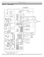
Page 23: ...23 WIRING DIAGRAMS Figure 12 Control Module Damper is not an option ...
Page 37: ...Date Service Performed Company Name Tech Initials Company Address Phone ...
Page 38: ...NOTES ...
Page 39: ...Date Service Performed Company Name Tech Initials Company Address Phone ...
Page 40: ...UTICA BOILERS 2201 Dwyer Avenue Utica NY 13501 web site www ecrinternational com ...


