18
9.
Support Spacing:
Do not restrict thermal expansion movement of the
vent. The vent pipe must expand and contract freely
with temperature change. Each run of vent piping shall
be supported as follows:
A. Z-Flex stainless steel vent piping requires a loose
fi
tting metal strap or similar support at each joint
at a maximum of 4 feet between supports.
B. Heat-Fab stainless steel vent piping requires a
support for every 6 feet of horizontal piping run.
The support must be secured using at least #10
fasteners to a solid material (solid masonry or
wood framing or blocking.) Do not fasten to drywall
sheathing using hollow wall anchors. Each support
will be 1½ inch lower than the previous support
when spaced 6 feet apart.
C. Flex-L stainless steel vent piping requires a loose
fi
tting metal strap or similar support at each joint
at a maximum of 4 feet between supports.
D. ProTech stainless steel vent piping requires one
loose
fi
tting FasNSeal support strap for every 6’ of
horizontal vent.
10.
If the horizontal vent must go through a crawl space
or other unheated space, the cool temperatures will
likely cause the
fl
ue gases to continuously condense
inside the vent pipe. Do not insulate the vent pipe. It
must be visible for monthly inspection. Insure that the
vent pipe is properly pitched away from the boiler, with
no low spots, so that condensate in the vent will drain
away from the boiler. An insulated enclosure or chase,
with access for inspection and servicing of the vent,
may be required to prevent freezing of liquid conden-
sate. Consult the vent pipe manufacturer’s instructions
for speci
fi
c guidelines.
11.
At beginning of each heating season and monthly
during the heating season, check all vent pipes and
vent terminal to make sure there are no obstructions.
Periodically clean the screen in the vent terminal.
OPTIONAL HORIZONTAL VENTING INSTRUCTION
HORIZONTAL VENTING INSTRUCTIONS
Horizontal venting with a power venter is an alternate
method of sidewall venting. This boiler is CSA listed for
sidewall venting with standard single wall galvanized or
Type B vent pipe when using the following power venter
kits, which were speci
fi
cally sized for these boilers:
Table 3 - Field Controls
Number Of
Boiler Sections
Field Controls
Power Venter
2, 3, 4, 5
SWG-4D
6, 7
SWG-5D
Some possible reasons for using a power venter for
sidewall venting:
1.
May be preferred by local codes.
2.
Need a vent piping run beyond 30’ (9.1m) (but not
more than 50’ (15.2m)).
3.
The boiler installation site experiences gusting or high
winds. A power venter can help prevent the boiler from
short cycling due to gusting or high winds by providing
vent exhaust pressures greater than the boiler’s
induced draft blower alone.
4.
When installers or homeowners prefer a negative
pressure vent system instead of a positive pressure
vent system.
5.
May be more cost effective than stainless steel
venting, particularly at longer vent length.
The Field Controls power vent kit includes either a
SWG-II-4HD or SWG-II-5 power venter, a MG-1 4”
barometric draft controller, and the CK-43D controls kit.
Con
fi
rm that installing a power venter is an option allowed
by local codes. Follow the speci
fi
c power venter installation
instructions issued with the power venter kits. Although
the power venter is equipped with its own fan, the fan on
the boiler remains in place and is unaltered when a power
venter is used.
When sidewall venting,
fl
ue gases must be vented to a
point in relation to the prevailing wind so that they may
freely disperse without being blown back at the building
causing discoloration, or into the building through doors or
windows causing odors. Also, under certain conditions
fl
ue
gases will condense, forming moisture. In such cases, steps
should be taken to prevent building materials at the vent
terminal from being damaged by the exhausted
fl
ue gas.
When installing single wall galvanized vent pipe for power
venting follow the speci
fi
c power venter installation
instructions for layout, location of the barometric draft
control and termination connections.
When joining and sealing the single wall galvanized or Type
B vent piping, use RTV silicone sealant with a minimum
temperature rating of 400°F. For 3” vent pipe runs, begin
with the female end of the vent pipe over the boiler’s
induced draft blower outlet. For 4” vent pipe runs begin
with the galvanized 3” to 4” increaser
fi
tting (included in
the boiler’s parts bag) over the induced draft blower outlet.
Then follow by placing the female end of the 4” vent pipe
over the increaser
fi
tting.
When joining pieces of single wall galvanized vent pipe, a
substantial bead of silicone should be used at the joint to
insure a leak proof connection.
Summary of Contents for UTICA BOILERS SVB II Series
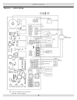
Page 23: ...23 WIRING DIAGRAMS Figure 12 Control Module Damper is not an option ...
Page 37: ...Date Service Performed Company Name Tech Initials Company Address Phone ...
Page 38: ...NOTES ...
Page 39: ...Date Service Performed Company Name Tech Initials Company Address Phone ...
Page 40: ...UTICA BOILERS 2201 Dwyer Avenue Utica NY 13501 web site www ecrinternational com ...


