vii - near boiler pipinG
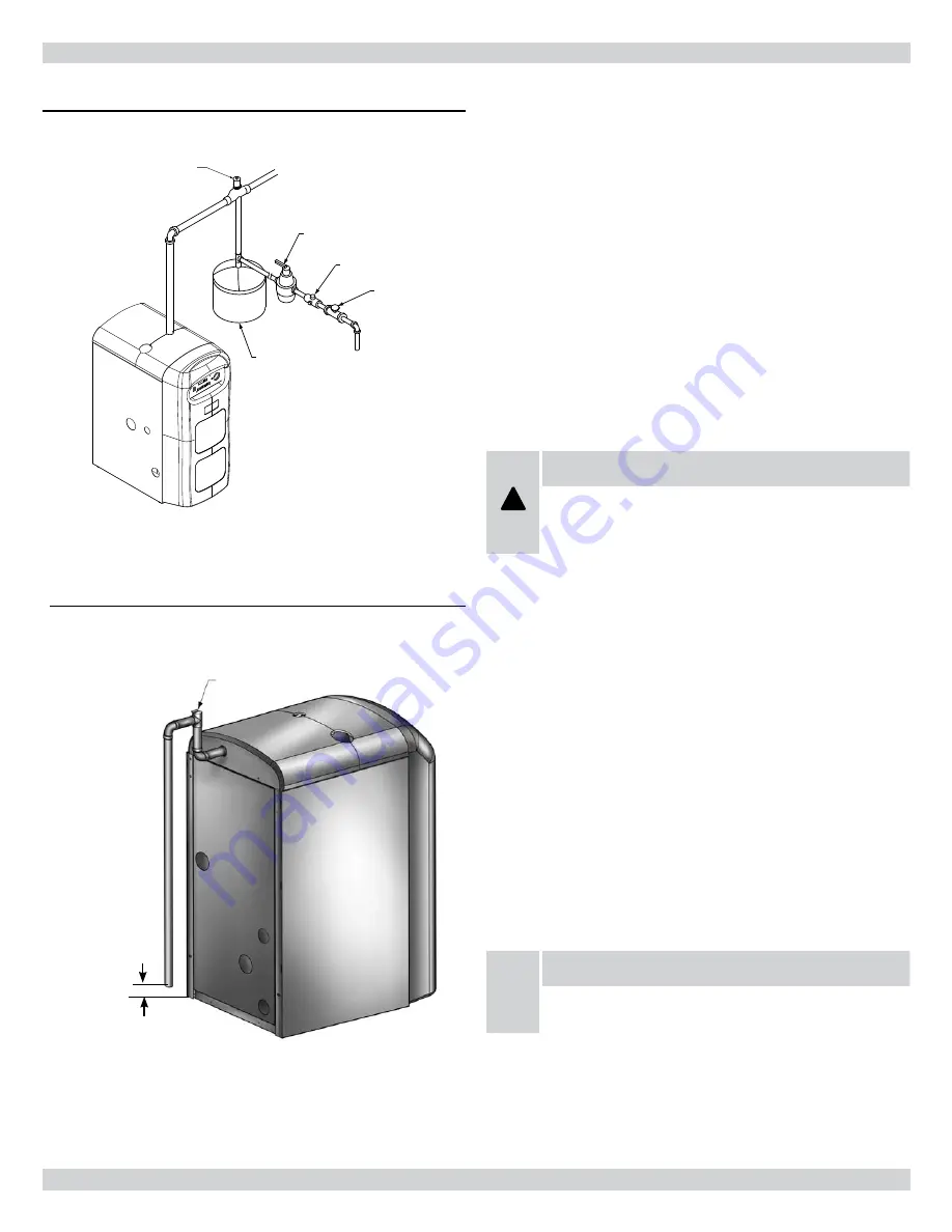
pressure relief valve / temperature pressure Gauge
The boiler is furnished with a relief valve in the boiler parts bag. Pro-
vide ¾” piping from the supplied relief valve to a local floor drain,
but leave an air gap between piping and drain. No shutoff of any
description shall be placed between safety relief valve and the boiler,
or on the discharge pipes between such safety valve and the atmo-
sphere. Installation of the safety relief valve shall conform to ANSI/
ASME Boiler and Pressure Vessel Code, Section IV. The manufac-
turer is not responsible for any water damage. Check local codes for
maximum height from discharge piping to floor.
supply & return lines
The packaged boiler unit is set up to receive 1¼” NPT return piping
from the rear of the unit with an option for left or right return con-
nections. 1¼” NPT supply piping exits the boiler jacket at the top of
the unit.
!
CAUTION
NOTE: On some boilers the circulator pump and isolation
valves are furnished in a carton inside the boiler cabinet
and can be installed at the installer preferred location.
condensate drain piping
The condensate trap is integral to the boiler. Use the supplied 1/2”
PVC tee, then transition to ½” pipe and fittings for PVC condensate
drain line. Condensate drain line to be pitched down to floor drain
at a minimum of ¼” per foot.
The ½” diameter schedule 40 PVC condensate drain piping and pipe
fittings must conform to ANSI standards and ASTM D1785. Sched-
ule 40 PVC cement and primer must conform to ASTM D2564. In
Canada, use CSA or ULC certified schedule 40 PVC drain pipe and
cement.
A condensate pump with a reservoir (not furnished) may be used
to remove condensate to a drain line (sanitary line) above boiler if a
floor drain is not available or is inaccessible.
filling the condensate trap with water
NOTICE
IMPORTANT: On initial start up the condensate trap must
be manually filled with water.
The following are the steps required to initially fill the condensate
trap for start up, these steps are only required at the initial start up or
if maintenance requires draining of the condensate trap:
Pour about 1 cup of cold tap water into the vent drain line using
1.
the 1/2” PVC vent tee provided with the boiler.
Check local codes
for maximum dis-
tance from floor.
FLOOR
figure 7 - relief valve discharge piping
Pressure Relief Device
GATE VALVE
REDUCED PRESSURE
BACKFLOW PREVENTER
FEED
WATER
PRESSURE
REDUCING VALVE
AIR SCOOP
DIAPHRAGM TYPE
EXPANSION TANK
SUPPLY PIPING
figure 6 - diaphragm type expansion tank piping
11
Summary of Contents for UTICA BOILERS UB95M-200
Page 26: ...26 ...
Page 45: ...45 ...
Page 46: ...46 ...
Page 47: ...NOTES ...
Page 48: ...Date Service Performed Company Name Tech Initials Company Address Phone ...


