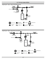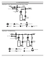
Xvi - pipinG and wirinG appendiX
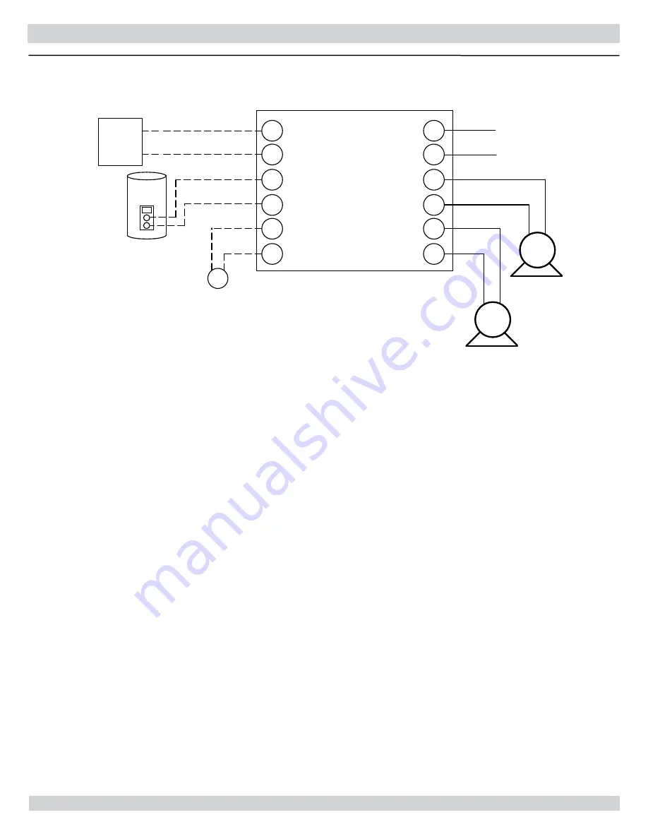
CH C1
L1
T-STAT
L2
CH C2
DHW C2
DHW C1
DHW T2
A2
A1
DHW T1
CH T2
CH T1
OUTDOOR
AIR SENSOR
BOILER CONTROL PANEL
DHW CIRC
L1
120 VAC
L2
CH
CIRC
Note: The CH & DHW Circulator connections on the boiler will only support
a pump with a 1 amp rating or less.
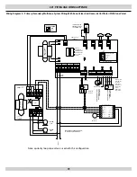
boiler control wiring diagram: single zone system with domestic hot water priority
28
Summary of Contents for UTICA BOILERS UB95M-200
Page 26: ...26 ...
Page 45: ...45 ...
Page 46: ...46 ...
Page 47: ...NOTES ...
Page 48: ...Date Service Performed Company Name Tech Initials Company Address Phone ...


