background image

Chapter 3

BSWI-D USER MANUAL

47

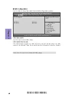
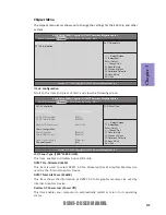
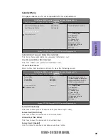
This page enables you to exit system setup after saving or without saving the
changes.

Exit Menu

Save Options

Use this item enables you to save the options that you have made.

Save Changes

Use this item enables you to save the changes that you have made.

Discard Changes

Use this item enables you to discard any changes that you have made.

Restore Defaults

Use this item enables you to restore the system defaults.

Save as User Defaults

Use this item enables you to save the changes that you have made as user defaults.

Restore User Defaults

Use this item enables you to restore user defaults to all the setup options.

Save Changes and Exit

Use this item enables you to exit system setup after saving the changes.

Discard Changes and Exit

Use this item enables you to exit system setup without saving any changes

.

Save Changes and Reset

Use this item enables you to reset the system setup after saving the changes.

Discard Changes and Reset

Use this item enables you to reset system setup without saving any changes.

Boot Override

Use this item enables you to set the device order.

+/-  :Change Opt.

Enter : Select

          F1:General Help



Aptio Setup Utility - Copyright (C) 2015 American Megatrends, Inc.



:Select Screen

:Select Item

           F2:Previous Values

          F3:Optimized Defaults

          F4:Save & Exit

          ESC:Exit


Version 2.17.1249. Copyright (C) 2015 American Megatrends, Inc.

Main


Advanced    Chipset    M.I.B X   Boot   Security    

Exit

Save Changes and Exit

Discard Changes and Exit
Save  Changes and Reset
Discard Changes and Reset

Save Options

Save Changes
Discard Changes

Restore Defaults
Save as User Defaults
Restore User Defaults

Boot Override

UEFI: KingstoneDataTraveler 2.0PMAP, Partition 1

Exit system setup after saving
the changes.

Summary of Contents for BSWI-D

Page 1: ...s been tested and found to comply with the limits for a Class B digital device pursuant to Part 15 of the FCC Rules These limits are designed to provide reasonable protection against harmful interference in a residential instal lation This equipment generates uses and can radiate radio frequency energy and if not installed and used in accordance with the instructions may cause harmful interference...

Page 2: ...age 7 page 25 page 49 Installing the Motherboard IntroducingtheMotherboard Provides information on us ing the BIOS Setup Utility Describes the motherboard software Limits and methods of mesurement of radio disturbance char acteristics of information technology equipment EN 55022 EN 61000 3 2 Disturbances in supply systems caused EN 61000 3 3 Disturbances in supply systems caused by household appli...

Page 3: ... Case Components 21 TABLE OF CONTENTS Preface i Chapter 1 1 Introducing the Motherboard 1 Introduction 1 PakageContents 1 Specifications 2 Motherboard Components 4 I OPorts 6 Chapter 3 25 UsingBIOS 25 About the Setup Utility 25 The Standard Configuration 25 Entering the Setup Utility 25 Resetting the Default CMOS Values 26 UsingBIOS 26 BIOS Navigation Keys 27 Main Menu 28 Advanced Menu 28 Chipset ...

Page 4: ...tallingunderWindows7 8 8 1 49 Running Setup 49 ManualInstallation 51 ECSUtilitySoftware IntelligentEZUtility Optional 51 Chapter 5 53 Trouble Shooting 53 Startupproblemsduringassembly 53 Startupproblemsafterprolonguse 54 Maintenanceandcaretips 54 BasicTroubleshootingFlowchart 55 ...

Page 5: ... 0 ports two USB 2 0 ports at the rear panel and one 2 5 pin USB 2 0 header supports additional two USB 2 0 ports and one 1 5 pin USB 2 0 header supports one USB 2 0 port and one USB 3 0 port two USB 3 0 ports at the rear panel The motherboard is equipped with advanced full set of I O ports in the rear panel including one DC_IN port one DC_Out port optional one PS 2 Keyboard PS 2 Mouse connectors ...

Page 6: ...n 19V power connector 1 x 4 pin CPU_FAN connector 1 x 4 pin SYS_FAN connector 1 x 2 5 pinUSB 2 0 header supports additional two USB 2 0 ports 1 x 1 5 pin USB 2 0 header supports additional one USB 2 0 port 2 x Serial ATA 6Gb s connectors 1 x BZ 1 x Front Panel switch LED header 1 x Front Panel audio header 1 x Clear CMOS jumper 1 x BKLT_PWR jumper optional 1 x LVDS select jumper LCD_PWR optional 1...

Page 7: ...p Bundled Software Support F7 hot key for boot up devices option Supports PgUp clear CMOS Hotkey Has PS2 KB Model only Note 1 Microsoft NET Framework 3 5 is required 2 Free bundle software is including ECS DVD Cyberlink Media Suite Norton Anti Virus Muzee 1 x Case open header 1 x SATA power connector optional 1 x Amplifier Speaker header Supports eBLU 1 eDLU eSF 3rd Party Bundled Software Cyberlin...

Page 8: ...Chapter 1 4 BSWI D USER MANUAL Motherboard Components ...

Page 9: ...DISP_BRT LVDS brightness control header optional 10 LCD_PWR LVDS select jumper optional 11 LVDS LVDS connector optional 12 MINIPCIE mini PCIE half card slot 13 F_USB1 2 5 pin Front panel USB 2 0 header 14 F_USB2 1 5 pinFront panel USB 2 0 header 15 F_AUDIO Front panel audio header 16 SATA_PWR SATA power connector optional 17 MONO MONO jumper 18 SPEAKER Amplifier speaker header 19 SATA1 2 Serial AT...

Page 10: ...ay device to the HDMI port 7 USB 3 0 Ports Use the USB 3 0 port to connect USB 3 0 device 8 LAN Port Connect an RJ 45 jack to the LAN port to connect your computer to the Network 9 USB 2 0 Ports Use the USB 2 0 ports to connect USB 2 0 devices 10 Line in blue It can be connected to an external CD DVD player Tape player or other audio devices for audio input 11 Line out green It is used to connect ...

Page 11: ...n the motherboard Place the motherboard over the mounting brackets and secure the motherboard onto the mounting brackets with screws Follow these safety precautions when installing the motherboard Wear a grounding strap attached to a grounded device to avoid damage from static electricity Discharge static electricity by touching the metal case of a safely grounded object before working on the moth...

Page 12: ... Components No Components 1 LCD_PWR optional 3 MONO 2 BKLT_PWR optional 4 CLR_CMOS 2 3 Checking Jumper Settings This section explains how to set jumpers for correct configuration of the motherboard 1 LCD_PWR LVDS Select Jumper optional ...

Page 13: ...Chapter 2 BSWI D USER MANUAL 9 2 BKLT_PWR Backlight Power Jumper optional 3 MONO MONO Jumper ...

Page 14: ...tability after clearing CMOS we recommend users to enter the main BIOS setting page to Load Default Settings and then Save and Exit Setup The following illustration shows the location of the motherboard jumpers Pin 1 is labeled 4 CLR_CMOS Clear CMOS Jumper ...

Page 15: ...andle the modules only by their edges Do not touch the components or metal parts Always wear a grounding strap when you handle the modules You must install one module in the slot Total memory capacity is 8 GB Refer to the following to install the memory modules Install the DIMM module into the slot and press it firmly down until it seats correctly Check that the cutouts on the DIMM module edge con...

Page 16: ...res and capabilities With these efficient facilities you can increase the motherboard s capabilities by adding hardware that performs tasks that are not part of the basic system Before installing an add on card check the documentation for the card carefully If the card is not Plug and Play you may have to manually configure the card before installation MINIPCIE Slot The mini PCIE half card support...

Page 17: ...ot 3 Secure the metal bracket of the card to the system case with a screw For some add on cards for example graphics adapters and network adapters you have to install drivers and software before you can begin using the add on card Follow these instructions to install an add on card Follow these instructions to install a wireless card or TV tuner card 1 Insert a wireless card or TV tuner card into ...

Page 18: ...on on connecting the motherboard s optional devices No Components No Components 1 COM1 2 6 F_USB1 2 LPT 7 F_USB2 3 CASE 8 F_AUDIO 4 DISP_BRT optional 9 SATA_1 2 5 LVDS optional 1 COM1 2 Onboard Serial Port Headers Connect serial port extension brackets to these headers to add serial ports to your system ...

Page 19: ...This header can be used to connect to the printer scanner or other devices 3 CASE Chassis Intrusion Detect Header This detects if the chassis cover has been removed This functiion needs a chassis equipped with intrusion detection switch and needs to be enabled in BIOS ...

Page 20: ...cable to the LED panel and connect the other small end to the slot on the motherboard 2 Due to the chipset limitation using dual displays LVDS AIO VGA or LVDS AIO HDMI will cause the problem that you may not enter BIOS setup or have the display problem 4 DISP_BRT LVDS Brightness Control Header optional ...

Page 21: ...ports to the motherboard 6 F_USB1 2 5 pin Front Panel USB 2 0 Header Please make sure that the USB cable has the same pin assignment as indicated above A different pin assignment may cause damage or system hang up The motherboard has one 1 5 pin USB 2 0 header supporting one USB 2 0 port 7 F_USB2 1 5 pin Front Panel USB 2 0 Header Please make sure that the USB cable has the same pin assignment as ...

Page 22: ...ference only AC 97 Audio Configuration To enable the front panel audio connector to support AC97 Audio mode The front panel audio header allows the user to install auxiliary front oriented microphone and line out ports for easier access This header supports HD audio by default If you want connect an AC 97 front panel audio to HD onboard headers please set as below picture 8 F_AUDIO Front Panel Aud...

Page 23: ...ick off the option of Using Front Jack Detect For reference only SATA 1 2 connectors support the Serial ATA 6Gb s device simpler disk drive cabling and easier PC assembly It eliminates limitations of the current Parallel ATA interface But maintains register compatibility and software compatibility with Parallel ATA 9 SATA1 2 Serial ATA Connectors ...

Page 24: ...ctors on the motherboard and follow the illustration below to install the SATA hard drives Installing Serial ATA Hard Drives To install the Serial ATA SATA hard drives use the SATA cable that supports the Serial ATA protocol This SATA cable comes with a SATA power cable You can connect either end of the SATA cable to the SATA hard drive or the connector on the motherboard Refer to the illustration...

Page 25: ...mponents No Components No Components 1 CPU_FAN 4 SPEAKER 2 F_PANEL 5 SYS_FAN 3 SATA_PWR optional 6 ATX19V optional 1 5 CPU_FAN CPU Cooling FAN Connector SYS_FAN System Cooling FAN Connector Users please note that the fan connector supports the CPU cooling fan of 1 1A 2 2A 26 4W max at 12V Connect the CPU cooling fan cable to CPU_FAN Connect the system cooling fan connector to SYS_FAN ...

Page 26: ...ng the reset function requires connecting pin 5 and 7 to a momentary con tact switch that is normally open When the switch is closed the board resets and runs POST Power Switch Supporting the power on off function requires connecting pins 6 and 8 to a momen tary contact switch that is normally open The switch should maintain contact for at least 50 ms to signal the power supply to switch on or off...

Page 27: ...BSWI D USER MANUAL 23 Chapter 2 3 SATA_PWR SATA Power Connector optional 4 SPEAKER Amplifier Speaker Header ...

Page 28: ...case power supply connector to ATX19V This concludes Chapter 2 The next chapter covers the BIOS The ATX19V power connector is used to provide power to the CPU When installing 4 pin power cable the latches of power cable and the ATX19V match perfectly Connecting 4 pin power cable 4 pin power cable ...

Page 29: ...ttings made in the Setup Utility affect how the computer performs Before using the Setup Utility ensure that you understand the Setup Utility options This chapter provides explanations for Setup Utility options The Standard Configuration A standard configuration has already been set in the Setup Utility However we recommend that you read this chapter in case you need to make any changes in the fut...

Page 30: ...r the option Use the cursor arrow keys to scroll through the items in the submenu Resetting the Default CMOS Values When powering on for the first time the POST screen may show a CMOS Settings Wrong message This standard message will appear following a clear CMOS data at factory by the manufacturer You simply need to Load Default Settings to reset the default CMOS values Note Changes to system har...

Page 31: ...hrough the items on a menu Modifies the selected field s values F2 PreviousValues F3 Optimized Defaults F1 GeneralHelp ESC Exits the current menu Enter Select In this manual default values are enclosed in parenthesis Submenu items are denoted by a triangle F4 Save Exit For the purpose of better product maintenance the manufacture reserves the right to change the BIOS items presented in this manual...

Page 32: ...ate Wed 03 18 2015 SystemTime 00 00 07 Change Opt Enter Select F1 General Help Choosethesystemdefault language Aptio Setup Utility Copyright C 2015 American Megatrends Inc Select Screen Select Item F2 Previous Values F3 Optimized Defaults F4 Save Exit ESC Exit Version 2 17 1249 Copyright C 2015 American Megatrends Inc Main Advanced Chipset M I B X Boot Security Exit Change Opt Enter Select F1 Gene...

Page 33: ...ust use an ATX power supply in order to use this feature Resume By RTC Alarm Disabled EUP Function Enabled This item allows user to enable or disable EUP support Power LED Type Dual Color LED This item shows the type of the Power LED The system can be turned off with a software command If you enable this item the system can automatically resume at a fixed time based on the system s RTC realtime cl...

Page 34: ... American Megatrends Inc Select Screen Select Item F2 Previous Values F3 Optimized Defaults F4 Save Exit ESC Exit Version 2 17 1249 Copyright C 2015 American Megatrends Inc Main Advanced Chipset M I B X Boot Security Exit SoCTemperature 25 C SystemTemperature 24 C CPU Fan Speed 2732 RPM SystemFanSpeed 0 RPM CPU Voltage 0 858V DIMM Voltage 1 386V 12V 12 078V 5V 5 005V 3 3V 3 432V Smart Fan Function...

Page 35: ...e Slope Select PWM of the smart fan Press Esc to return to the PC Health Status page SoC Temperature System Temperature CPU Fan Speed System Fan Speed CPU Voltage DIMM Voltage 12V 5V 3 3V System Component Characteristics These items display the monitoring of the overall inboard hardware health events such as System CPU temperature CPU DIMM voltage CPU system fan speed etc Press Esc to return to th...

Page 36: ... Esc to return to the Advanced Menu page Change Opt Enter Select F1 General Help Aptio Setup Utility Copyright C 2015 American Megatrends Inc Select Screen Select Item F2 Previous Values F3 Optimized Defaults F4 Save Exit ESC Exit Version 2 17 1249 Copyright C 2015 American Megatrends Inc Main Advanced Chipset M I B X Boot Security Exit LAN Configuration Onboard LAN Controller Enabled Enabled Disa...

Page 37: ...turn to the Advanced Menu page Change Opt Enter Select F1 General Help Aptio Setup Utility Copyright C 2015 American Megatrends Inc Select Screen Select Item F2 Previous Values F3 Optimized Defaults F4 Save Exit ESC Exit Version 2 17 1249 Copyright C 2015 American Megatrends Inc Main Advanced Chipset M I B X Boot Security Exit ACPI Settings ACPI Sleep State S3 Suspend to RAM SelectthehighestACPIsl...

Page 38: ... 17 1249 Copyright C 2015 American Megatrends Inc Main Advanced Chipset M I B X Boot Security Exit CPU Configuration Socket 0 CPU Information CPU Speed 1360 MHz 64 bit Supported Limit CPUID Maximum Disabled Bi directional PROCHOT Enabled Intel Virtualization Technology Enabled PowerTechnology Energy Efficient Enhanced Halt C1E Enabled Socket specific CPU Information Change Opt Enter Select F1 Gene...

Page 39: ...l HT technology or not Intel VT X Technology Supported This item shows the computer supports Intel VT X technology or not L1 Data Cache 24 KB X 4 This item shows the size of CPU L1 Data Cache memory L1 Code Cache 32 KB X 4 This item shows the size of CPU L1 Code Cache memory L2 L3Cache 1024 KB X 2 Not present These items show the size of CPU L2 L3 Cache memory Press Esc to return to the CPU Config...

Page 40: ... SATA Mode AHCI Use this item to select SATA mode Press Esc to return to the Advanced Menu page Change Opt Enter Select F1 General Help Aptio Setup Utility Copyright C 2015 American Megatrends Inc Select Screen Select Item F2 Previous Values F3 Optimized Defaults F4 Save Exit ESC Exit Version 2 17 1249 Copyright C 2015 American Megatrends Inc Main Advanced Chipset M I B X Boot Security Exit SATACo...

Page 41: ...1 General Help Aptio Setup Utility Copyright C 2015 American Megatrends Inc Select Screen Select Item F2 Previous Values F3 Optimized Defaults F4 Save Exit ESC Exit Version 2 17 1249 Copyright C 2015 American Megatrends Inc Main Advanced Chipset M I B X Boot Security Exit USB Configuration All USB Devices Enabled Legacy USB Support Enabled USB Support Parameters Legacy USB Support Enabled Use this...

Page 42: ...allows you to enable or disable serial port Device Settings IO 3F8h IRQ 4 This item shows the information of the device settings Change Settings Auto Use this item to change device settings Press Esc to return to the Super IO Configuration page Super IO Chip IT8625 This item shows the information of the super IO chip Change Opt Enter Select F1 General Help Aptio Setup Utility Copyright C 2015 Amer...

Page 43: ... Security Exit Serial Port 2 Configuration Scroll to this item and press Enter and view the following screen Serial Port Enabled This item allows you to enable or disable serial port Device Settings IO 2F8h IRQ 3 This item shows the information of the device settings Change Settings Auto Use this item to change device settings Press Esc to return to the Super IO Configuration page Serial Port 2 Co...

Page 44: ... following screen Parallel Port Enabled This item allows you to enable or disable serial port Device Settings IO 378h IRQ 5 This item shows the information of the device settings Change Settings Auto Use this item to change device settings Device Mode Standard Parallel This item is used for Printer port mode selection it can be set to Standard Parallel Port Mode SPP or EPP Mode Press Esc to return...

Page 45: ...p Utility Copyright C 2015 American Megatrends Inc Select Screen Select Item F2 Previous Values F3 Optimized Defaults F4 Save Exit ESC Exit Version 2 17 1249 Copyright C 2015 American Megatrends Inc Main Advanced Chipset M I B X Boot Security Exit LCD Panel Type SoC Configuration LCD Panel Type 1920 1080Bits24 DVMT Pre Allocated 64M DVMT Total Gfx Mem 256MB Restore AC Power Loss PowerOff Audio Con...

Page 46: ...isabled This item enables or disables the warning if the case is opened up and the item below indicates the current status of the case Chassis Opened No This item indicates whether the case has been opened Audio Controller Enabled This item enables or disables Audio controller Change Opt Enter Select F1 General Help Aptio Setup Utility Copyright C 2015 American Megatrends Inc Select Screen Select ...

Page 47: ... ESC Exit Enter Select CPU Frequency 80 0 MHz This item shows the frequency of CPU reference clock CPU Ratio 17 This item shows the max CPU ratio supported Celeron Intel R CPU 1 36 GHZ This is display only field and displays the information of the CPU installed in your computer CPU Speed 1 36 GHz This item shows the CPU speed Memory Frequency 1066 MHz This item shows the memory frequency Total Mem...

Page 48: ...perating system from the installing UEFI USB Flash drive Press Enter to see the submenu Change Opt Enter Select F1 General Help Aptio Setup Utility Copyright C 2015 American Megatrends Inc Select Screen Select Item F2 Previous Values F3 Optimized Defaults F4 Save Exit ESC Exit Version 2 17 1249 Copyright C 2015 American Megatrends Inc Main Advanced Chipset M I B X Boot Security Exit Windows 7 or o...

Page 49: ... Previous Values F3 Optimized Defaults F4 Save Exit ESC Exit Version 2 17 1249 Copyright C 2015 American Megatrends Inc Set Administrator Password Administrator Password Status Not Installed User Password Status Not Installed Administrator Password SecureBootmenu Change Opt Enter Select F1 General Help Aptio Setup Utility Copyright C 2015 American Megatrends Inc Select Screen Select Item F2 Previo...

Page 50: ... to modify Secure Boot variables Secure Boot Mode Standard This item is used to select secure boot mode When you select standard mode secure boot policy is fixed when you select custom mode the image execution policy and secure boot key databases are changeable ...

Page 51: ...anges and Exit Use this item enables you to exit system setup without saving any changes Save Changes and Reset Use this item enables you to reset the system setup after saving the changes Discard Changes and Reset Use this item enables you to reset system setup without saving any changes Boot Override Use this item enables you to set the device order Change Opt Enter Select F1 General Help Aptio ...

Page 52: ...bootable system disk Refer to Windows online help for information on creating a bootable system disk 4 Download the Flash Utility and new BIOS file from the manufacturer s Web site Copy these files to the bootable device 5 Turn off your computer and insert the bootable device in your computer You might need to run the Setup Utility and change the boot priority items on the Advanced BIOS Features S...

Page 53: ...h for all software and drivers available on the disk Open Windows Explorer and show the contents of the support disk Click Exit button to close the Auto Setup window Browse CD Click the Setup button to select and run the software installation program Click the Utilities button to select and install ECS Intelligent Utility Information Follow these instructions to install device drivers and software...

Page 54: ...ll the items Drivers and software are automatically installed in sequence Follow the onscreen instructions confirm commands and allow the computer to restart a few times to complete the installation Windows 8 will show the following screen after system restart you must select Desktop in the bottom left to install the next driver 4 Click Next to run the Installation Wizard An item installation scre...

Page 55: ... SETUP EXE that automatically detects your operating system before installation Other drivers have the setup program located in the operating system subfolder Manual Installation ECS Utility Software Intelligent EZ Utility Optional ECS Intelligent EZ Utility provides friendly interfaces under Windows O S which makes your computing more easily and conveniently If the driver you want to install does...

Page 56: ...assle by listing all the latest drivers online Just select the one you prefer and start to download and install the drivers eSF eSF Smart Fan utility provides easy and safe way to adjust fan speed in accordance with your PC s system loading and temperature It has five modes to adjust fan speed in a safe range without entering the BIOS to optimize your system cooling environment Microsoft NET Frame...

Page 57: ...m short circuit 3 Check the CPU FAN connector is connected to the motherboard 4 For Intel platforms check the pins on the CPU socket for damage or bent A bent pin may cause failure to boot and sometimes permanent damage from short circuit b Power is on fans are running but there is no display 1 Make sure the monitor is turned on and the monitor cable is properly connected to the PC 2 Check the VGA...

Page 58: ...puter like any electrical appliance requires proper care and maintenance Here are some basic PC care tips to help prolong the life of the motherboard and keep it running as best as it can 1 Keep your computer in a well ventilated area Leave some space between the PC and the wall for sufficient airflow 2 Keep your computer in a cool dry place Avoid dusty areas direct sunlight and areas of high mois...

Page 59: ... o r p t o n y r o m e m M M I D e r u l i a f y r o m e m r o d e t r e s n i s p e e b t r o h s 8 d n a p e e b g n o l 1 f I d e t c e t e d t o n A G V s e Y s e Y n e e r c s T S O P t a t l a H s e Y O M C R L d n a S C t s e r t r a A M R t c a t n o c l i a f f I s e Y o N e u s s i e c i v e d l a r e h p i r e P m e l b o r p D D H r o r r e p u t e s S O M C d S O M C R L C o t e e n t...

Page 60: ...BSWI D USER MANUAL Chapter 5 56 Memo ...

Reviews: