background image

iii

TTTTTABLE OF CONTENTS

ABLE OF CONTENTS

ABLE OF CONTENTS

ABLE OF CONTENTS

ABLE OF CONTENTS

Preface

                      i

Chapter 1

1

Introducing the Motherboard

1

Introduction......................................................................................1
Feature...............................................................................................2
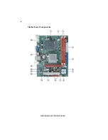
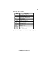
Motherboard Components.............................................................4

Chapter 3

   27

Using BIOS

27

About the Setup Utility.................................................................27

The Standard Configuration...................................................27

Entering the Setup Utility........................................................27

Resetting the Default CMOS Values

.......................................28

Using BIOS

.....................................................................................

29

Standard CMOS Setup...........................................................30
Advanced Setup......................................................................31

Advanced Chipset Setup.........................................................33

Chapter 2

  7

 7 7

 7 7

Installing the Motherboard                                                                           7

Safety Precautions...........................................................................7
Choosing a Computer Case............................................................7

Installing the Motherboard in a Case...........................................7
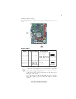
Checking Jumper Settings..............................................................8

Setting Jumpers........................................................................8
Checking Jumper Settings........................................................9

    Jumper Settings........................................................................9


Installing Hardware.......................................................................10

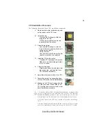
Installing the Processor.........................................................10

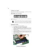
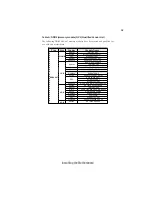
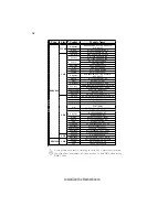
Installing Memory Modules...................................................12

Expansion Slots......................................................................15

            Connecting Optional Devices................................................17

Installing a Hard Disk Drive/CD-ROM/SATA Hard Drive..20

      Connecting I/O Devices..............................................................22

Connecting Case Components....................................................23

Front Panel Header................................................................25

Summary of Contents for G31T-M9

Page 1: ...tested and found to comply with the limits for a Class B digital device pursuant to Part 15 of the FCC Rules These limits are designed to provide reasonable protection against harmful interference in a residential installa tion This equipment generates uses and can radiate radio frequency energy and if not installed and used in accordance with the instructions may cause harmful inter ference to ra...

Page 2: ...egulations Cet appareil numérique de la classe B respecte toutes les exigences du Réglement sur le matériel brouilieur du Canada AbouttheManual The manual consists of the following Describes features of the motherboard Go to H page 1 Describes installation of motherboard components Go to H page 7 Provides information on using the BIOS Setup Utility Go to H page 27 Describes the motherboard soft wa...

Page 3: ...OS 29 Standard CMOS Setup 30 Advanced Setup 31 Advanced Chipset Setup 33 Chapter 2 7 7 7 7 7 Installing the Motherboard 7 Safety Precautions 7 Choosing a Computer Case 7 Installing the Motherboard in a Case 7 CheckingJumperSettings 8 Setting Jumpers 8 Checking Jumper Settings 9 Jumper Settings 9 InstallingHardware 10 Installing the Processor 10 Installing Memory Modules 12 Expansion Slots 15 Conne...

Page 4: ...thout Saving 41 Updating the BIOS 42 Chapter 4 43 43 43 43 43 UsingtheMotherboardSoftware 43 AbouttheSoftwareDVD ROM CD ROM 43 Auto installing underWindowsVista 7 43 Running Setup 44 ManualInstallation 46 UtilitySoftwareReference 46 Chapter 5 47 47 47 47 47 Trouble Shooting 47 Startupproblemsduringassembly 47 Start up problems after prolong use 48 Maintenance and care tips 48 Basic Troubleshooting...

Page 5: ...uming DDR2 800 MHz High resolution graph ics via one PCI Express slot intended for Graphics Interface is fully compliant to the PCI Express Base Specification revision 1 1 The ICH7 Southbridge supports one PCI slot which is PCI v2 3 compliant In addi tion one PCI Express x1 slot is supported fully compliant to the PCI Express Base Specification revision 1 1 It implements an EHCI compliant interfac...

Page 6: ...Mb and 1 Gb DDR2 DRAM technologies for x8 and x16 devices One 16 lane PCI Express port intended for Graphics Attach compatible to the PCI Express Base Specifi cation revision 1 1 Enhanced DMAController interrupt controller and timer functions Compliant with PCI Express Base Specification Revi sion 1 1 Compliant with PCI 2 3 specification Integrated SATA 3 0 Gb s Host Controller Integrated USB 2 0 ...

Page 7: ... IEEE802 3u IEEE802 3ab Wake On LAN WOL by Magic Packet Frame Link Change Integrated PHY for 10 100 1000 Mbps IEEE 802 3x compliant flow control support Three power supplies 2 5V 1 8V and 1 2V PCI Express base 1 1 compliant Two PS 2 ports for mouse and keyboard One VGA port Four USB ports One LAN port Audio jacks for microphone line in and line out The motherboard has a full set of I O ports and c...

Page 8: ...4 IntroducingtheMotherboard Motherboard Components ...

Page 9: ...Clear CMOS jumper 8 F_PANEL Front Panel switch LED header 9 F_USB Front Panel USB header 10 SATA1 2 Serial ATA connectors 11 LPT Onboard parallel port header 12 F_AUDIO Front panel audio header 13 PCI1 32 bit add on card slot 14 COM Onboard serial port header 15 PCIE PCI Express x1 slot 16 PCIEX16 PCI Express x16 graphics card slot Rear Panel USB PS 2 Power Select Jumper for PS 2 S3 wake up only 1...

Page 10: ...6 IntroducingtheMotherboard Memo ...

Page 11: ...case Make sure that your case supports all the features required Secondly this motherboard supports two enhanced IDE drives Make sure that your case has sufficient power and space for all drives that you intend to install Most cases have a choice of I O templates in the rear panel Make sure that the I O template in the case matches the I O ports installed on the rear edge of the motherboard This m...

Page 12: ...than one pin are numbered When setting the jumpers ensure that the jumper caps are placed on the correct pins The illustrations show a 2 pin jumper When the jumper cap is placed on both pins the jumper is SHORT If you re move the jumper cap or place the jumper cap on just one pin the jumper is OPEN This illustration shows a 3 pin jumper Pins 1 and 2 are SHORT SHORT OPEN Do not over tighten the scr...

Page 13: ...m CLR_CMOS KBMPWR 3 pin 1 2 VCC 2 3 5VSB 1 To avoid the system instability after clearing CMOS we recommend users to enter the main BIOS setting page to Load Default Settings and then Save Changes and Exit 2 Make sure the power supply provides enough 5VSB voltage before selecting the 5VSB function 3 It is required that users place the KBMPWR cap onto 2 3 pin rather than 1 2 pin as default if you w...

Page 14: ...tomatically determines the CPU clock frequency and system bus frequency for the processor You may be able to change the settings in the system Setup Utility We strongly recommend that you do not over clock processors or other components to run faster than their rated speed This motherboard has an LGA775 socket When choosing a processor consider the performance requirements of the system Performanc...

Page 15: ... lever CPU is locked completely F Apply thermal grease on top of the CPU G Fasten the cooling fan supporting base onto the CPU socket on the motherboard H Make sure the CPU fan is plugged to the CPU fan connector Please refer to the CPU cooling fan user s manual for more detail installation procedure CPU Installation Procedure The following illustration shows CPU installation components 1 To achie...

Page 16: ...ules Installation Procedure Refer to the following to install the memory modules 1 This motherboard supports unbuffered DDR2 SDRAM 2 Push the latches on each side of the DIMM slot down 3 Align the memory module with the slot The DIMM slots are keyed with notches and the DIMMs are keyed with cutouts so that they can only be installed correctly 4 Check that the cutouts on the DIMM module edge connec...

Page 17: ...667 512 MB Samsung PC2 5300U 555 12 D3 AU01GE667C5KBGC 78 01G9O 9K5 Apacer 1GB UNB PC2 5300 CL5 Corsair VS1GB667D2 Hexon HYNT7AUDR 30M48 Kingston KVR667D2N5 Micron MT8HTF12864AY 667E1 AL7E8E63B 6E1T AL7E8F63J 6E1 PSC AL7E8F73C 6E1 1 GB Samsung GOLD BAR M378T2863DZS 0742 Aeneon AET860UD00 30DB08X Apacer 78 A1G9O 9K4 Hynix HYMP125U64AP8 Y5 AB A 0623 Hexon HYNT8AUDR 30M88 Kingston KVR667D2N5 2G LeadM...

Page 18: ...nscend 507301 1571 1 GB Unifosa GU341G0ALEPR6B2C6CE A DATA RED A DATAM2OMI6H3J4720L1C5Z Aeneon AET860UD00 25DC08X Apacer 78 A1GAO 9K4 CORSAIR CM2X2048 6400C5 Geil PLATINUM EDITION Geil BOXED 2GB DS Hexon ELPT8AUDR 25M88 KVR800D2N6 2G SP Kingston KVR800D2N5 2G Micron MT16HTF25664AY 800E1 Nanya NT2GT64U8HD0BY AD PSC AL8E8F73C 8E1 Qimonda HYS64T256020EU 25F C2 Samsung M378T5663QZ3 CF7 Silicon Power S...

Page 19: ... carefully If the card is not Plug and Play you may have to manually configure the card before installation This motherboard is equipped with one standard PCI slot PCI stands for Peripheral Component Interconnect and is a bus standard for expansion cards which for the most part is a supplement of the older ISA bus standard The PCI slot on this board is PCI v2 3 compliant PCI1 Slot PCIEX16 Slot The...

Page 20: ...or of the add on card into the expansion slot Ensure that the edge connector is correctly seated in the slot 3 Secure the metal bracket of the card to the system case with a screw 2 The onboard PCI interface does not support 64 bit SCSI cards 1 For some add on cards for example graphics adapters and network adapters you have to install drivers and software before you can begin using the add on car...

Page 21: ...mbly It elimi nates limitations of the current Parallel ATA interface But maintains register com patibility and software compatibility with Parallel ATA 1 Ground 2 TX 3 TX 4 Ground 5 RX 6 RX 7 Ground Pin Signal Name Pin Signal Name F_AUDIO Front Panel Audio header for Azalia This header allows the user to install auxiliary front oriented microphone and line out ports for easier access 1 PORT 1L 2 ...

Page 22: ...nt Panel USB Power 2 USBPWR Front Panel USB Power 3 USB_FP_P0 USB Port 0 Negative Signal 4 USB_FP_P1 USB Port 1 Negative Signal 5 USB_FP_P0 USB Port 0 Positive Signal 6 USB_FP_P1 USB Port 1 Positive Signal 7 GND Ground 8 GND Ground 9 Key Nopin 10 USB_FP_OC0 Overcurrentsignal Pin Signal Name Function COM Onboard serial port header Connect a serial port extension bracket to this header to add a seco...

Page 23: ...sed to connect to the printer scanner or other devices 1 STROBE 14 AFD 2 PD0 15 ERROR 3 PD1 16 INIT 4 PD2 17 SLCTIN 5 PD3 18 Ground 6 PD4 19 Ground 7 PD5 20 Ground Pin Signal Name Pin Signal Name 8 PD6 21 Ground 9 PD7 22 Ground 10 ACK 23 Ground 11 BUSK 24 Ground 12 PE 25 Ground 13 SLCT 26 Key ...

Page 24: ...ach runs up to 3 0 Gb s To get better system performance we recommend users connect the CD ROM to the IDE channel and set up the hard drives on the SATA ports About SATAConnectors Your motherboard features two SATA connectors supporting a total of two drives SATA refers to Serial ATA Advanced Technology Attachment is the standard inter face for the IDE hard drives which are currently used in most ...

Page 25: ...allation This motherboard does not support the Hot Plug function 1 Attach either cable end to the connector on the motherboard 2 Attach the other cable end to the SATA hard drive 3 Attach the SATA power cable to the SATA hard drive and connect the other end to the power supply ...

Page 26: ... PS 2 port to connect a PS 2 keyboard VGA Port Connect your monitor to the VGA port LAN Port Connect an RJ 45 jack to the LAN port to connect your computer to the Network USB Ports Use the USB ports to connect USB devices Audio Ports Use the three audio ports to connect audio devices The first jack is for stereo line in signal The second jack is for stereo line out signal The third jack is for mic...

Page 27: ...pply connector to ATX_POWER 5 Connect the auxiliary case power supply connector to ATX12V The ATX_POWER 24 pin connector allows you to connect to ATX v2 x power supply With ATX v2 x power supply users please note that when installing 24 pin power cable the latches of power cable and the ATX_POWER match perfectly Connecting 24 pin power cable 24 pin power cable The ATX12V power connector is used to...

Page 28: ...d 3 Sense Sensor 4 PWM PWM Pin Signal Name Function 2 12V Power 12V Pin Signal Name Pin Signal Name 1 3 3V 13 3 3V 3 Ground 15 Ground 4 5V 16 PS_ON 5 Ground 17 Ground 6 5V 18 Ground 7 Ground 19 Ground 8 PWRGD 20 5V 9 5VSB 21 5V 10 12V 22 5V 11 12V 23 5V 12 3 3V 24 Ground 2 3 3V 14 12V ATX12V ATX 12V Power Connector Pin Signal Name 4 12V 3 12V 2 Ground 1 Ground SPK Internal speaker Pin Signal Name ...

Page 29: ...rovides visual indication that data is being read from or written to the hard drive For the LED to function properly an IDE drive should be connected to the onboard IDE interface The LED will also show activity for devices connected to the SCSI hard drive activity LED connector Power Switch Supporting the power on off function requires connecting pins 6 and 8 to a momen tary contact switch that is...

Page 30: ...26 InstallingtheMotherboard Memo ...

Page 31: ...tures The settings made in the Setup Utility affect how the computer performs Before using the Setup Utility ensure that you understand the Setup Utility options This chapter provides explanations for Setup Utility options The Standard Configuration A standard configuration has already been set in the Setup Utility However we recommend that you read this chapter in case you need to make any change...

Page 32: ...ault Settings Supervisor Password User Password Save Exit Setup Exit Without Saving Move F10 Save ESC Exit Value Enter Select F9 Load Default Settings F1 General Help Resetting the Default CMOS Values When powering on for the first time the POST screen may show a CMOS Settings Wrong message This standard message will appear following a clear CMOS data at factory by the manufacturer You simply need...

Page 33: ...e the highlight to other options When an option is highlighted execute the option by pressing Enter Some options lead to pop up dialog boxes that prompt you to verify that you wish to execute that option Other options lead to dialog boxes that prompt you for infor mation Some options marked with a triangle lead to submenus that enable you to change the values for the option Use the cursor arrow ke...

Page 34: ...00 02 00 Primary IDE Master Not Detected Primary IDE Slave Not Detected SATA1 Not Detected SATA2 Not Detected IDE BusMaster Enabled Move F10 Save ESC Exit Enter Select Value F9 Load Default Settings F1 General Help CMOS Setup Utility Copyright C 1985 2005 American Megatrends Inc Primary IDE Master Help Item Primary IDE Master Slave SATA1 2 Your computer has one IDE channel and each channel can be ...

Page 35: ...sable 32Bit Data Transfer Press Esc to return to the Standard CMOS Setup page IDE BusMaster Enabled This item enables or disables the DMA under DOS mode We recommend you to leave this item at the default value Press Esc to return to the main menu setting page Advanced Setup This page sets up more advanced information about your system Handle this page with caution Any changes can affect the operat...

Page 36: ...troller mode APIC provides symmetric multi processing SMP for sys tems allowing support for up to 60 processors Boot Up Numlock Status On This item defines if the keyboard Num Lock key is active when your system is started Quick Power on Self Test Enabled Enable this item to shorten the power on testing POST and have your system start up faster You might like to enable this item after you are conf...

Page 37: ...y application DVMT Mode Select DVMT Mode This item allows you to select the DVMT operating mode DVMT FIXED Memory 256MB When set to Fixed Mode the graphics driver will reserve a fixed portion of the system memory as graphics memory according to system and graphics requirements Press Esc to return to the main menu setting page HPET Enabled This item enables or disables HPET High Precision Event Tim...

Page 38: ...IDE interface OnBoard SATA Controller Enhanced This item allows you to enable or disable the onboard SATA controller Onboard LAN Function Enabled Use this item to enable or disable the onboard LAN function Onboard LAN Boot ROM Disabled Use this item to enable or disable the booting from the onboard LAN or a network add in card with a remote boot ROM installed Onboard AUDIO Function Enabled Use thi...

Page 39: ...IRQ to the parallel port USB Functions Enabled Use this item to enable or disable the USB function Legacy USB Support Enabled Use this item to enable or disable support for legacy USB devices Setting to Auto allows the system to detect the presence of USB device at startup If detected the USB controller legacy mode is enabled If no USB device is detected the legacy USB support is disabled Soft Off...

Page 40: ... return to its operating status Resume on RTC Alarm Disabled The system can be turned off with a software command If you enable this item the system can automatically resume at a fixed time based on the system s RTC realtime clock Use the items below this one to set the date and time of the wake up alarm You must use an ATX power supply in order to use this feature Press Esc to return to the main ...

Page 41: ...lect F9 Load Default Settings F1 General Help Move Select which graphics controller to use as the primary boot device PC Health Status On motherboards support hardware monitoring this item lets you monitor the parameters for critical voltages temperatures and fan speeds Init Display First PCI Use this item to select which graphics controller to use as the primary boot devices Hardware Health Event...

Page 42: ...isabled Enabled Options Press Esc to return to the PC Health Status page Move F10 Save ESC Exit Enter Select Value F9 Load Default Settings F1 General Help System Component Characteristics These items display the monitoring of the overall inboard hardware health events such as System CPU temperature CPU DIMM voltage CPU system fan speed etc Shutdown Temperature Disabled Enable you to set the maxim...

Page 43: ...cturer Intel This item displays the information of current manufacturer of the CPU installed in your computer CPU Frequency 200MHz This item indicates the current CPU frequency Users can not make any change to this item Please noted that the frequency will be varied with different CPU Auto Detect DIMM PCI Clk Enabled When this item is enabled BIOS will disable the clock signal of free DIMM PCI slo...

Page 44: ...nge the password Help Item Supervisor Password Not Installed Change Supervisor Password Press Enter Load Default Settings This option opens a dialog box that lets you install stability oriented defaults for all appropriate items in the Setup Utility Select OK and then press Enter to install the defaults Select Cancel and then press Enter to not install the defaults Change Supervisor Password Press...

Page 45: ... changes and exit or select Cancel to return to the main menu User Password Not Installed This item indicates whether a user password has been set If the password has been installed Installed displays If not Not Installed displays User Password This page helps you install or change a password Help Item CMOS Setup Utility Copyright C 1985 2005 American Megatrends Inc User Password Press Esc to retu...

Page 46: ...new BIOS file from the manufacturer s Web site Copy these files to the bootable device 5 Turn off your computer and insert the bootable device in your com puter You might need to run the Setup Utility and change the boot priority items on the Advanced BIOS Features Setup page to force your computer to boot from the bootable device 6 At the C or A prompt type the Flash Utility program name and the ...

Page 47: ...undled products Below you can find a brief description of each software program and the location for your motherboard version More information on some pro grams is available in a README file located in the same directory as the software Before installing any software always inspect the folder for files named README TXT or something similar These files may contain important information that is not ...

Page 48: ...ms such as Windows XP Vista 7 Always go to the correct folder for the kind of OS you are using In install the software execute a file named SETUP EXE by double clicking the file and then following the instructions on the screen Exit The EXIT button closes the Auto Setup window Utilities Tab Lists the software utilities that are available on the disk Information Tab Displays the path for all softwa...

Page 49: ...ons are recom mended 4 Click Next run the Installation Wizard An item installation screen appears 5 Follow the instructions on the screen to install the items Drivers and software are automatically installed in sequence Follow the onscreen instructions confirm commands and allow the computer to restart a few times to complete the installation ...

Page 50: ...e to the operating system subfolder and locate the readme text file README TXT or README DOC for information on installing the driver or software for your oper ating system Utility Software Reference All the utility software available from this page is Windows compliant They are provided only for the convenience of the customer The following software is fur nished under license and may only be use...

Page 51: ...wdrivers from the inside PC case This is to prevent damage from short circuit 3 Check the CPU FAN connector is connected to the motherboard 4 For Intel platforms check the pins on the CPU socket for damage or bent A bent pin may cause failure to boot and sometimes permanent damage from short circuit 5 Check the 12V power connector is connected to the motherboard 6 Check that the 12V power ATX conn...

Page 52: ...Optimised Default in the BIOS setup 2 Check the CPU cooler fan for dust Long term accumulation of dust will reduce its effectiveness to cool the processor Clean the cooler or replace a new one if necessary 3 Check that the 12V power ATX connectors are fully inserted into the motherboard connectors Make sure the latches of the cable and connector are locked into place 4 Remove the hard drive optica...

Page 53: ...act RMA No If 3 short beeps DIMM memory not properly inserted or memory failure If 1 long beep and 8 short beeps VGA not detected Yes Yes Halt at POST screen Yes R CMO L C S and restart If fail contact RMA Yes No Peripheral device issue HDD problem CMOS setup error d nee to CLRCMOS System fail to start or unstable a er modify BIOS se ng M CLR C OS and restart Turn on PSU switch or connect to wall ...

Page 54: ...50 TroubleShooting Memo ...

Reviews: