


9
Installing the Motherboard
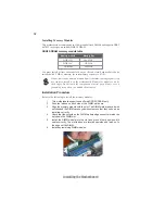
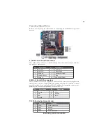
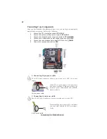
Checking Jumper Settings
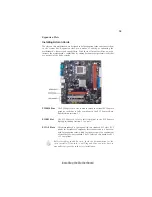
The following illustration shows the location of the motherboard jumpers. Pin 1 is
labeled.
Jumper Settings
To avoid the system instability after clearing CMOS, we recommend
users to enter the main BIOS setting page to “Load Default Settings”
and then “Save & Exit Setup”.
1 .
2. Make sure the power supply provides enough VCC5_DUAL voltage
before selecting the VCC5_DUAL function.
3. It is required that users place the USBPWR_F & USBPWR_R cap onto
2-3 pin rather than 1-2 pin as default if you want to wake up the
computer by USB/PS2 KB/Mouse.
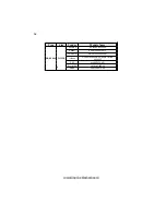
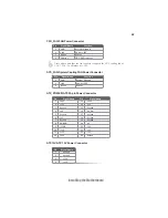
Jumper
Type
Description
Setting (default)
CLR_CMOS
3-pin CLEAR CMOS
1-2: NORMAL
2-3: CLEAR
Before clearing the
CMOS, make sure to
turn the system off.
3-pin
USBPWR_R
1-2: VCC
2-3: 5VSB
USB Power
Select Jumper
3-pin
USBPWR_F
1-2: VCC
2-3: 5VSB
USB Power
Select Jumper
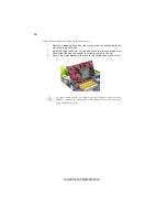
USBPWR_F
CLR_CMOS
1
1
USBPWR_R
1
Summary of Contents for GF7050VT-M
Page 1: ......
Page 2: ......
Page 10: ...4 IntroducingtheMotherboard Motherboard Components ...
Page 12: ...6 IntroducingtheMotherboard Memo ...
Page 48: ...42 Using BIOS Memo ...


