


17
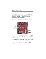
Chapter2: Motherboard Installation
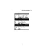
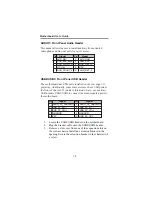
Please refer to the following list of the SW1 pin assignments.
Pin
Signal
Pin
Signal
1 HD) 2 FP PWR/SLP(+)
3 HD_LED_N(-) 4 FP PWR/SLP(-)
5 RESET_SW_N(-) 6 POWE)
7 RESE) 8 POWER_SW_N(-)
9 RSVD_DNU 10 KEY
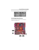
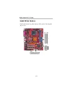
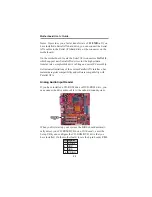
Connecting Optional Devices
Refer to the following for information on connecting the
motherboard’s optional devices:
1
SPK1
USB2
1
USB3
1
1
IR1
AUDIO1
1


